About SMARTElectrode Ribbon
All SMARTElectrode commands can be accessed in the ribbon of the same name. The ribbon is mode dependent and shows only the relevant commands.
The software distinguishes between the following modes:
- Process Ribbon in Assembly ModeCreate or Edit the assembly and manage electrodes.
- Design Ribbon in Active Component ModeEdit the design of active electrode, set blank and access advanced options.
Empty Session / Part Mode
- Assembly
- Assembly—Overflow.
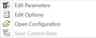
- Edit Parameters—customize information saved to components and models.
- Edit Options—customize application’s behavior.
- Open Configuration—open active configuration folder.
- Save Custom Base—save a custom electrode base to configuration. Only accessible if base template is opened from configuration.
- Assembly—Overflow.
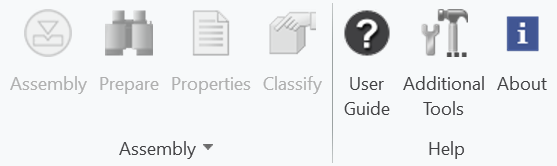
- Help
- User Guide—access the online help.
- Additional Tools—learn more about supplementary products from B&W Software.
- About—display the program information and copyright.
Process Ribbon in Assembly Mode

Use the commands in process ribbon to access the tools required to setup assembly, zero point and to create and edit electrodes:
- Assembly
- Assembly—create or edit assembly.
- Prepare—prepare workpiece geometry for processing.
- Properties—edit parameters for selected model.
- Classify—set object type for selected model.
- Assembly—Overflow (described above).
- Operation
- Zero—Cascade.
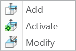
- Add—create new operation zero point.
- Activate—make selected operation active.
- Classify—set object type for selected model.
- Zero—Cascade.
- Electrode
- New—Cascade.
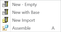
- New Empty—create new, empty electrode model and activate.
- New with Base—create new electrode from template including associated data like drawing or manufacturing files.
- New Import—create new electrode from STEP/IGES or Creo part file.
- Assemble—assemble electrode part from file.
- Activate—activate selected electrode component and switch to design ribbon.
- Repeat—assemble one or more selected electrode components again.
- Move—move one or more selected electrode components to new position.
- Copy—Cascasde.
- Copy—copy one or more selected electrode components to new models and add to assembly.
- Copy Template—copy new electrode from template and add to assembly.
- Check—check for interferences and evaluate effective contact area.
- Auto Interference—toggle automatic interference check on assembly level.
- New—Cascade.
- Organization
- Holder—add holder from library to electrodes..
- Manufacturing—create manufacturing files for Creo/NC from templates.
- Drawing—create documentation for assembly.
- Burnsheet—display parameters of whole assembly.
- Output—export assembly information to neutral formats like STEP, IGES or custom text files.
- Postprocessor—write assembly information for EDM programming interfaces. Requires additional license option.
- View
- Electrodes—show or hide electrode models.
- Workpieces—show or hide workpiece models.
- Style—Cascade.
- Electrodes Transparent—activate style to make electrode models transparent.
- Workpieces Transparent—activate style to make workpiece models transparent.
- Electrodes Wireframe—activate style to display electrode models as wireframe.
- Workpieces Wireframe—activate style to display workpieces as wireframe.
- Holders—show or hide holders.
- Surfaces—show or hide datum surfaces and quilts.
- Solids—show or hide solid geometry of electrodes.
- Show All—reset display of all models including objects hidden in modeltree.
- Display Start Positions—temporarily display start positions of electrode models.
- Display Secure Positions—temporarily display secure positions of electrode models.
- Help (as described above)
Design Ribbon in Activate Component Mode

Use the commands to access the tools required to detail electrode geometry in activated component mode as follows:
- Select
- Solid faces—select solid faces only. Datum surfaces are not selectable.
- Tooltip—select solid faces inside tool diameter or straight tool paths.
- Color—select connected solid faces by color.
- Shapes—access shape surface selection (Cascade).
- Cut—select surfaces from a cut.
- Cuts—select surfaces from a cut along with smaller surfaces intersecting them.
- Round—select surfaces of a round.
- Rounds—select surfaces of a round and connected surfaces of same size, type and convexity.
- Boss—select surfaces from a boss.
- Bosses—select surfaces from a boss along with smaller surfaces that intersect them.
- Coaxial—select coaxial surfaces.
- All Tops—select all top surfaces of solid not connected with FREE_FACE.
- Select—Overflow
 .
.
- Same—select surfaces of same type and size.
- Datum faces—only datum surfaces selectable.
- Quilts—only datum quilts selectable.
- Edges—only datum surface boundary selectable (one-sided edges).
- Loops—convert a selection of a boundary edge to a quilt boundary chain.
- All Loops—select all quilt boundary chains of all datum quilts.
- Get Data
- Cutout—Cascade.

- New Cutout—create a new solid and cutout for selected surfaces.
- Redefine Cutout—redefine a solid cutout group.
- Copy Geometry—create copy geom for selected surfaces.
- Mirror—mirror selected solid in active electrode component.
- Merge—merge selected solid in active electrode component.
- Split—copy sketched geometry from selected electrode to active electrode component.
- Cutout—Cascade.
- Datum—Cascade.
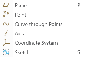
- Plane—create a datum plane.
- Point—create a datum point.
- Curve through Points—create a curve by using datum points.
- Axis—create a datum axis.
- Coordinate System—create a datum plane.
- Sketch—create a sketch on a planar reference.
- Surface—Cascade.
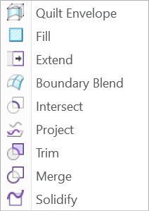
- Quilt Envelope—copy selected surfaces and enclose with a closed, rectangular quilt.
- Fill—create a flat surface.
- Extend—extend a contiguous one-sided edge of a quilt.
- Boundary Blend—create a surface by selection references in one or two directions.
- Intersect—create a curve at the intersection of two surfaces.
- Project—project a chain or a sketch onto solid or nonsolid surfaces, quilts or datum planes.
- Trim—cut or split quilts.
- Merge—merge two quilts together.
- Solidify—convert surface features or quilt geometry to solid geometry.
- Measure—Cascade.
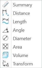
- Summary—various measurements.
- Distance—measure a distance.
- Length—measure a length.
- Angle—measure an angle.
- Diameter—measure a diameter.
- Area—measure an area.
- Volume—measure a volume.
- Transform—calculate the transformation matrix between coordinate sytems.
- Modeling
- Surface Replace—replace surface through surface.
- Surface Thicken—thicken selected surface as solid or cut.
- Surface Expand—Expand selected surfaces.
- Remove—remove selected surfaces from solid.
- Trim at datum—trim whole solid at selected datum plane.
- Pattern—create geometry pattern of electrode solid.
- Mirror—mirror electrode solid at datum plane.
- Attach—cascade.
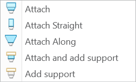
- Attach—expand and extrude selected top surfaces to FREE_FACE.
- Attach Straight—attach selected top surfaces straight to FREE_FACE.
- Attach Along—attach selected top surfaces along original surfaces to FREE_FACE.
- Attach and add support—expand and extrude selected top surface to FREE_FACE. Add extrusion as supporting geometry.
- Add support—add supporting geometry for selected top surfaces or complete solid.
- Modeling—Overflow.
- Surface Split—split all contours of a surface to separate surfaces.
- Add Block—add cuboid solid to remove geometry inside outline of selected surfaces.
- Cut Block—add cuboid cut to remove geometry inside outline of selected surfaces.
- Expand tangent—add tangent expansion to selected top surface.
- Expand conic—add conic expansion to selected top surface.
- Electrode
- Base—add a blank from library to solid.
- Properties—review and edit parameters of active electrode component.
- Check—check for interferences and analyze effective contact area.
- Auto Interference—toggle automatic interference check on active component level.
- Start Position—set a custom start position for active electrode component.
- CMM points—add, edit, remove CMM points on electrode solid.
- View (as described above)
- Help (as described above)