Std-Annotations and Std-Annotation Sets
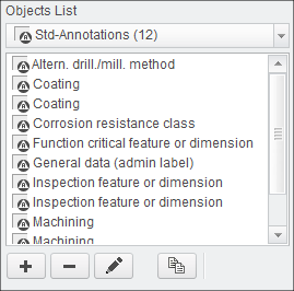
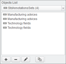
The Std-Annotation object contains the definition of an annotation that can be used in drawing mode or 3D mode. The technical means is a Creo
Symbol. Multiple symbols can be used in one Std-Annotation definition.The Std-Annotation Set is a collection of Std-Annotations.
How it works
A Std-Annotation set is automatically placed on the drawing or within the 3D model. The placement coordinates are defined during the definition
of the Std-Annotation Set or in the Drawing Format.
The selected Std-Annotations of an Std-Annotation Set will be stacked up at the defined location. You can use the Bottom-Up or Top-Down method for stacking.
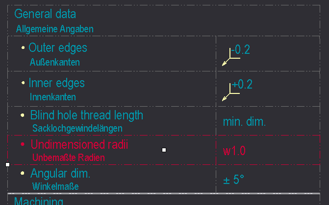
You may use a Separator and/or a Margin between the single Std-Annotation definitions.
Any kind of Creo symbol is valid.
Adding Std-Annotations
- Select Add new object
 or select Edit existing objects
  or use
  to copy an existing entry and modify from there.
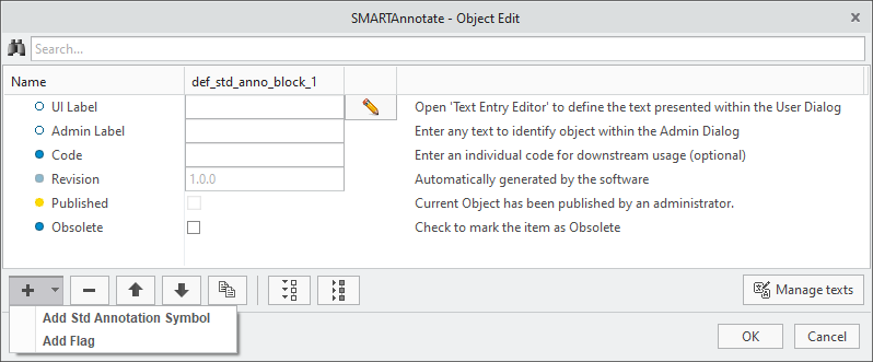
- The Object Edit dialog appears.
- The Object Edit dialog appears.
- Select
 to enter the UI Label that is displayed in the admin dialog.
 - (Optional) Enter an Admin Label that is used for distinction within the administration dialog.
- (Optional) Enter a Code (not implemented yet)
- The Revision will be iterated automatically every time you leave the definition dialog with OK and save the configuration. See the Versioning Objects section in the Appendix for more details-
- Check the Obsolete check box if you want to disable the Std-Annotation. It will remain within the configuration, but not anymore available for user selection.
- Choose Add new element Add Std Annotation Symbol
- A new Std Annotation Symbol entry is created within the Object Edit dialog
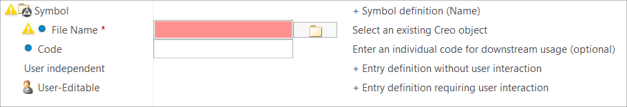
- A new Std Annotation Symbol entry is created within the Object Edit dialog
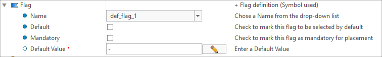
- (Optional) Choose Add new element Add Flag
- A new Flag entry is created within the Object Edit dialog. For every flag symbol that you want to display in the UI pull-down you have to create a separate Flag entry.
- A new Flag entry is created within the Object Edit dialog. For every flag symbol that you want to display in the UI pull-down you have to create a separate Flag entry.
- Check the Default check box to indicate which flag is the default one.
- Check the Mandatory check box to define if the user can deactivate the flag.
- Enter the Default Value, if you have a variable text within the underlying symbol.
Adding Std-Annotation Sets
- Select Add new object or select Edit existing objects or use to copy an existing entry and modify from there.
- The Object Edit dialog appears.
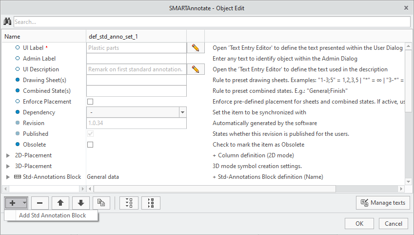
- The Object Edit dialog appears.
- Select to enter the UI Label that is displayed in the user dialog.
- (Optional) Enter an Admin Label that is used for distinction within the administration dialog.
- (Optional) Enter a UI Description.
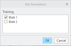
- Define a rule to pre-assign the Std-Annotation Set to Drawing Sheet(s). These sheets are then automatically selected for symbol creation by default without user interaction.
- Define Combined States which shall be selected by default for creating the Std-Annotation Set (3D mode only).
- Define the placement of the Std-Annotation stack
- The stack can be build using the top-down or bottom-up direction. The behavior is globally defined in the configuration file and can distinguish between 3D and 2D mode.
- The stack will be broken into the next column, if the breakpoint coordinates are reached while building the stack.
- The specified coordinate values refer to the origin of the used Creo symbol.
- 2D placement
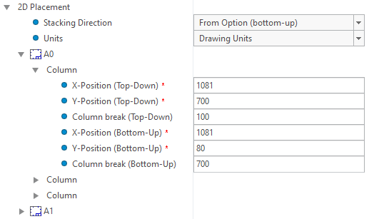
- Via ‘Stacking Direction’ it’s possible to define the direction in which the symbols are built.
- From Option (The value of option ‘expand_direction_2d’ will be used and is displayed in parenthesis)
- bottom-up
- top-down
- Via ’Units’, one can set the units in which the entered coordinates are to be interpreted. When the symbols are programmatically
created, this setting is compared to the detail option ‘drawing_units’ of the target drawing. If the units differ, a conversion
is done in order to express the entered coordinates in the units of the drawing. Possible values are:
- Drawing Units (No conversion is done, the coordinates are used as-is)
- inch
- foot
- mm (Millimeter)
- cm (Centimeter)
- m (Meter)
- The values entered here only take effect, if there are no values entered in the format definition.
- You can specify multiple columns for every used format size.
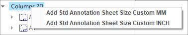
- (Optional) If you have defined custom size formats, you can add those formats to the list for entering the placement coordinates.
- Via ‘Stacking Direction’ it’s possible to define the direction in which the symbols are built.
- 3D placement
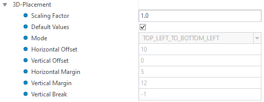
- Scaling Factor: Factor scaling the height of all symbols.
- Default Values: Use the values set for the corresponding configuration options or overwrite these defaults for this set.
- Mode: Origin and stacking direction (see option 'stacking_direction').
- Horizontal Offset: Horizontal offset in pixels between the symbols (see option 'symbol_to_symbol_spacing_horizontal').
- Vertical Offset: Vertical offset in pixels between the symbols (see option 'symbol_to_symbol_spacing_vertical').
- Horizontal Margin: Horizontal margin in pixels between the edge of the graphical area and the symbols (see option 'border_to_symbol_stack_spacing_horizontal').
- Vertical Margin: Vertical margin in pixels between the edge of the graphical area and the symbols (see option 'border_to_symbol_stack_spacing_vertical').
- Vertical Break: Position in pixels with respect to the stacking origin at which the symbol stack is wrapped into a new stack. '-1' sets the borders of the graphical model area (see option 'symbol_stack_break_vertical').
- Note: The coordinates range vertically from 0 to 840 and horizontally from 0 to 1000 starting at the bottom left corner of the graphics area. They are independent from the screen resolution.
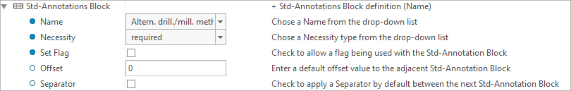
- Choose Add new element Add Std Annotation Block
- A new Std Annotation Block entry is created within the Object Edit dialog
- A new Std Annotation Block entry is created within the Object Edit dialog
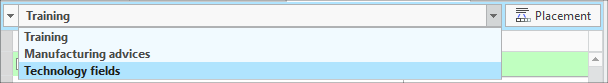
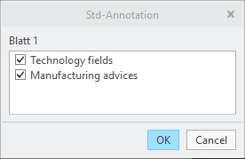
- Choose a Name of an existing Std-Annotation from the pull-down menu.
- Choose a Necessity from the pull-down menu.
- mandatory — this entry is pre-selected in the UI and cannot be deselected by the user
- required — this entry is preselected in the UI, but may be deselected by the user
- optional — this entry is not pre-selected in the UI
You can define the background colors of the three options in the configuration dialog. - Check the Set Flag check box to allow a flag to the Std-Annotation definition.
- Enter an Offset that is used to generate space between the current and the next definition. Default is 0.
- Check the Separator check box to use a separator symbol between Std-Annotation definitions. The Separator symbol is defined by the config option SEPARATOR_SYMBOL and can contain any kind of entities.
- Repeat for all intended Std-Annotation entities in the set.