To Add an Assembly to the Library
Download 00_library_asm to start with this chapter.
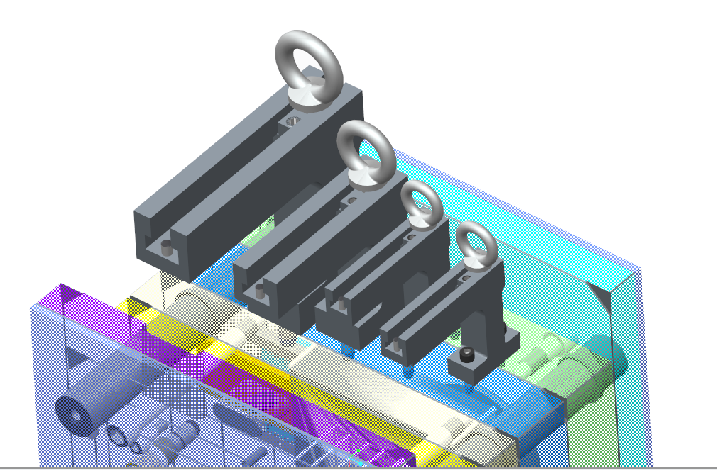
Adding assembly components to library is more complex than just adding a single part. In this chapter we will add the adjustable
transportation bar E1930 from the supplier Meusburger which can be seen in the picture below.
The Assembly Structure
Before adding the assembly to the EMX Library all containing single components need to be implemented.
The E1930 assembly contains the following parts:
| E1930_1: The transportation bar | 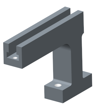 |
| E1903_2: The t-nut | 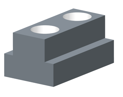 |
| E1270: A hoist ring | 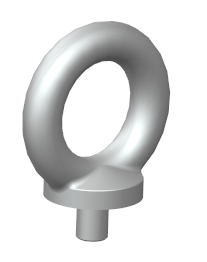 |
| E1200: 2 x socket head cap screws | 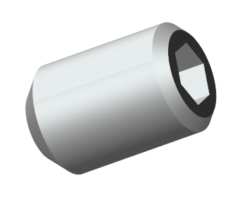 |
| E1230: A set screw | 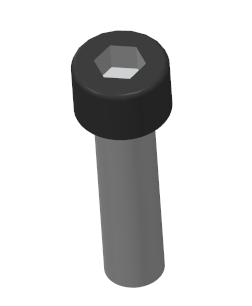 |
| E1300: 2 dowel pins | 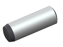 |
The components E1270, E1200, E1230 and E1300 are already available as regular EMX Components.
The bar E1930_1and the T-Nut E1930_2 have to be created.
Go to the Meusburger catalog and extract the data sheets for the components E1930_1 and E1930_2.
Use the regular Creo functions to create the PRT files.
The finished file can be used from the downloaded folder
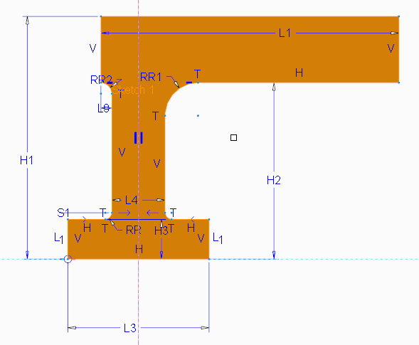
Design the component E1930_1
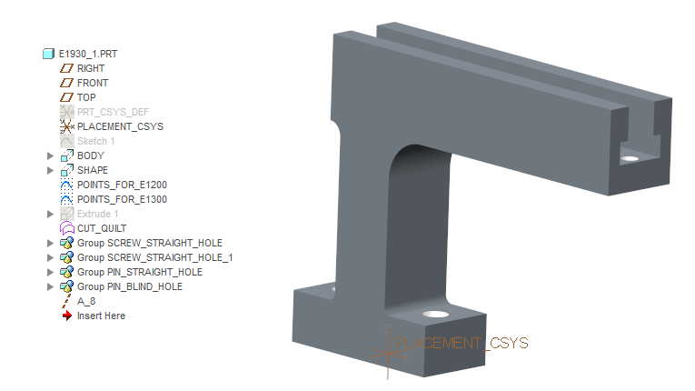
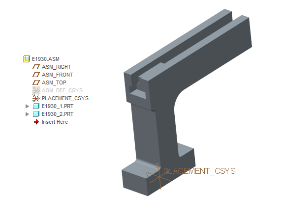
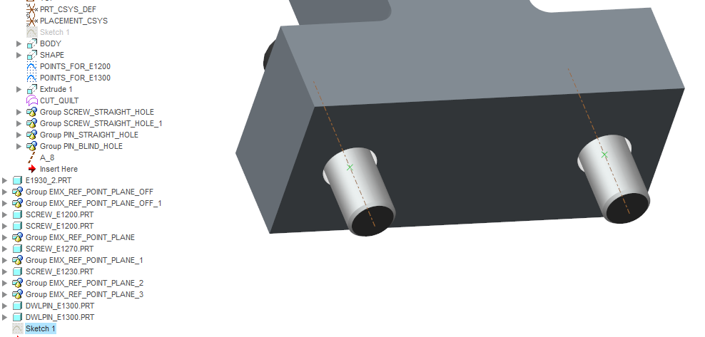
All model described in this chapter can be found in folder <install_tutorial>/models/library_asm. E1930_1 contains a couple of features:
- PLACEMENT_CSYS : Use this csys as assembly reference.
- BODY and SHAPE: This features describe the geometry.
- POINTS_FOR_E1300: points where the dowel pins E1300 will be placed in the assembly.
- POINTS_FOR_E1200: points where the screws E1200 will be placed in the assembly.
- CUT_QUILT: A quilt surface which surrounds the whole part this will be used as cut quilt later.
Add the component E1930_1 to the EMX Library
- Erase all models from the Creo session.
- Add the previously created part file E1903_1.PRT to the library folder <library_emx90>/tutorial and open the part.
- Add the component to the EMX library just as you have seen it the chapter To Add a Part to the Library.
- Use the PLACEMENT_CSYS as the assembly Reference.
- Make sure all dimensions which need to be varied are added as Nominal Dimensions
- Set up the Instances correctly.

- Use the CUT_QUILT feature as Cut Quilt.As a result you will find the E1930_1.dat file and the picture E1930_1.gif in <library_emx90>/tutorial folder.
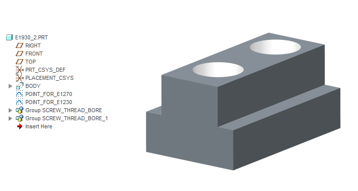
Design the component E1930_2
These are the important features:
- PLACEMENT_CSYS : Use this csys as assembly reference.
- BODY : This features describes the geometry.
- POINTS_FOR_E1270: points where the hoist ring E1270 will be placed in the assembly.
- POINTS_FOR_E1230: points where the set screws E1230 will be placed in the assembly.
Add the component E1930_2 to the EMX Library
- Erase all models from the Creo session.
- Add the previously created part file E1903_2.PRT in the library folder <library_emx90>/tutorial and open the part.
- Add the component to the EMX library just as you have seen it the chapter To Add a Part to the Library.Use the PLACEMENT_CSYS as the assembly Reference.
- Make sure all dimension which need to be varied are added as Nominal Dimensions
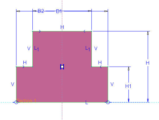
- Set up the Instances correctly.
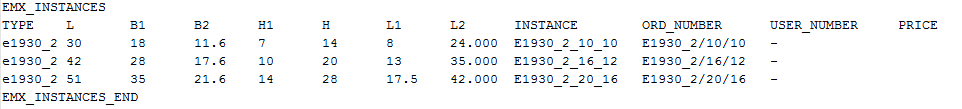 As a result you will find the E1930_2.dat file and the picture E1930_2.gif in <library_emx90>/tutorial folder.
Copy Screws and Dowel Pins to Library Folder
To design the assembly E1930.ASM copies of the template parts of dowel pin E1300, set screw E1230, head cap screw E1200 and
hoist ring E1270 are required in the library folder <library_emx>/tutorial.
- Copy screw_e1200.PRT from “<install_emx>/components/mm/screw” to “<library_emx>/tutorial”
- Copy screw_e1230.PRT from “<install_emx>/components/mm/screw” to “<library_emx>/tutorial”
- Copy screw_e1270.PRT from “<install_emx>/components/mm/screw” to “<library_emx>/tutorial”
- Copy dwlpin_e1300.PRT from “<install_emx>/components/mm/dowel_pin” to“<library_emx>/tutorial”
Design the Assembly E1930
- Erase all models from the Creo session.
- Create a new assembly and assemble the previously created components as seen in the picture below.
- Open EMX Assembly Project Modify
 .The Project dialog box appears.
 - Leave the dialog box again with OK. The Assembly is now considered to be an EMX project.
In the next steps the screws, pins and the hoist ring will be assembled.
- Click
 .
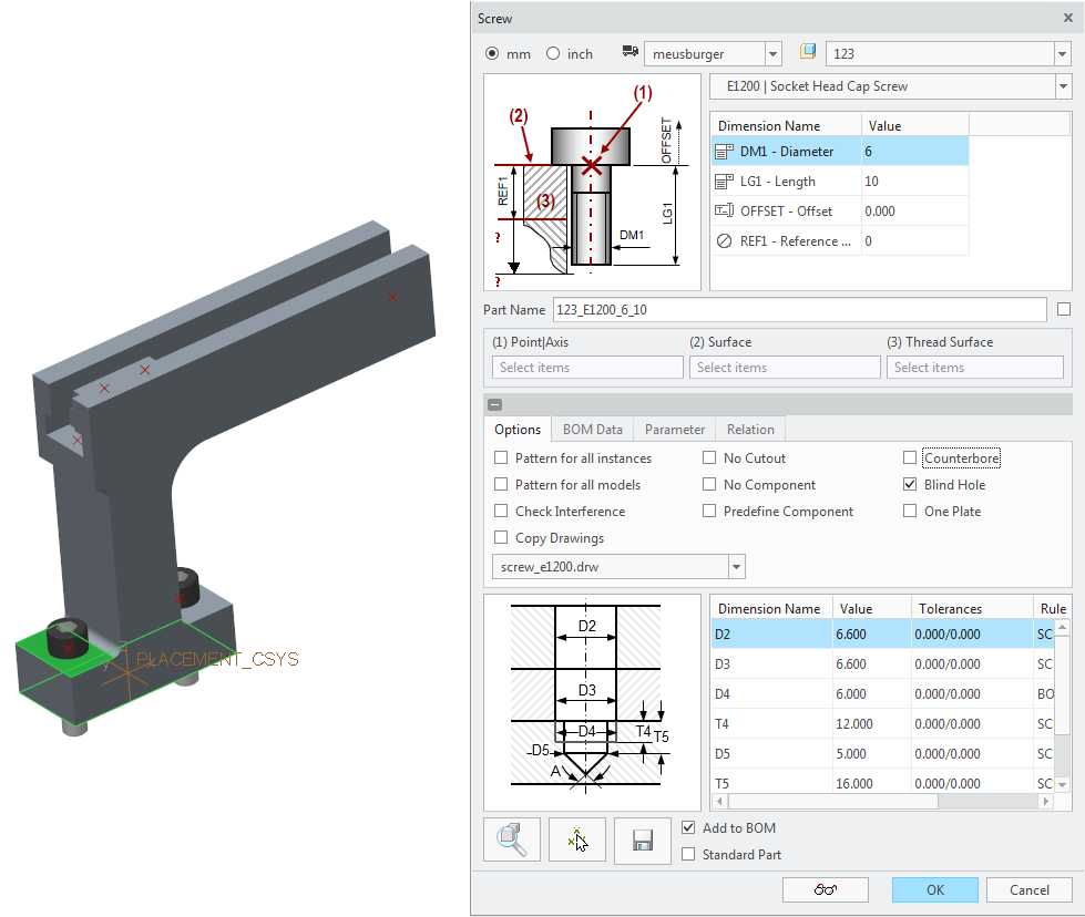
. - Assemble the E1200 component as seen in the picture below.
- Set Part Name to screw_E1200.This is essential to allow EMX to find the correct template model.
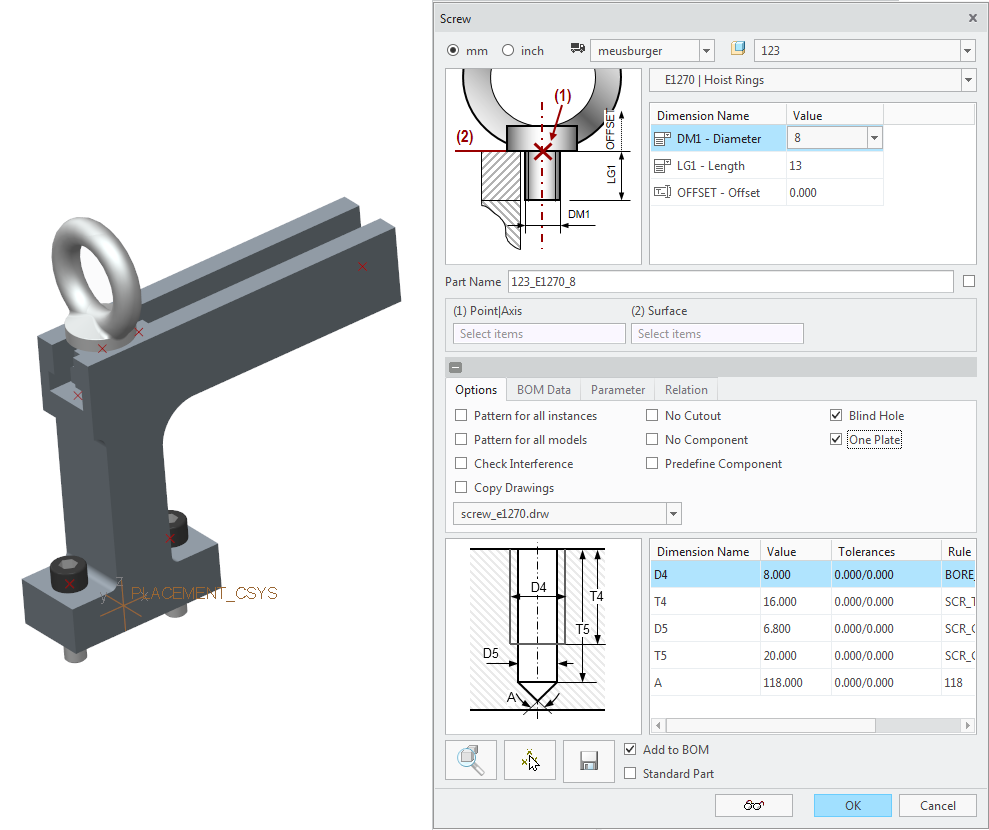
- Repeat the same steps for the hoist ring E1270.
- Set Part Name to screw_E1270.
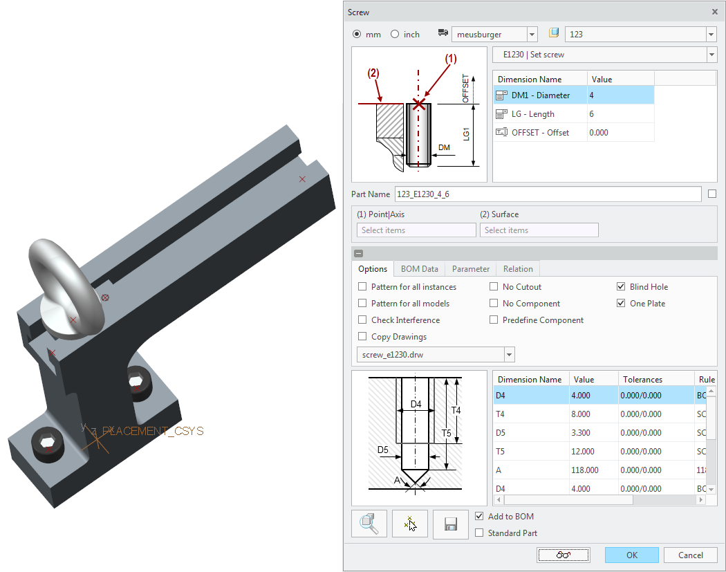
- Repeat the same steps for the set screw E1230.
- Set Part Name to screw_E1230.
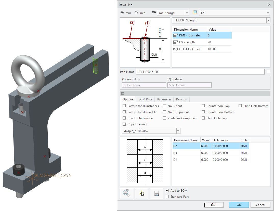
- Repeat the same steps for the dowel pins E1300.
- Set Part Name to dwlpin_E1300.
 The Assembly is completed.
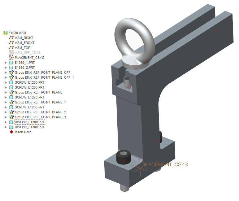
Add the assembly E1930 to the EMX Library
- Start
 .The Component Editor dialog box opens.
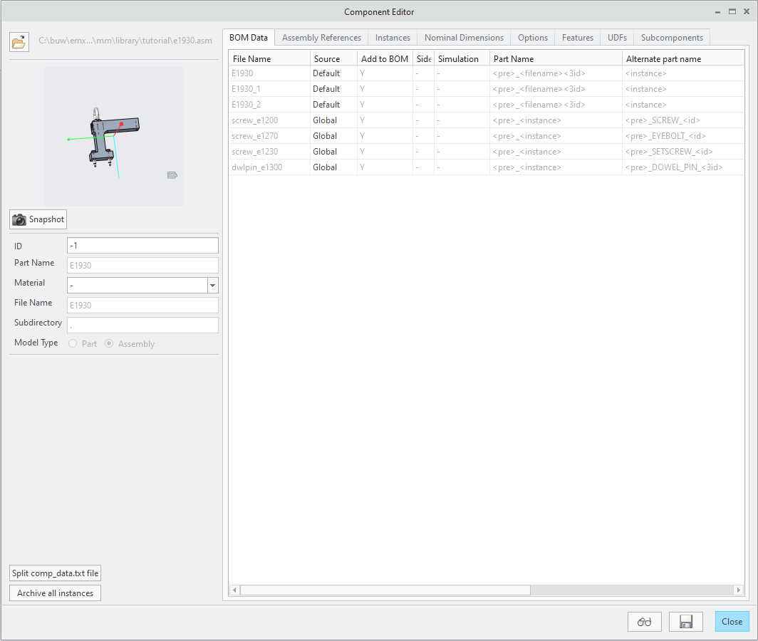
 - Click Open model or *.dat fileThe File Open dialog box appears. Select e1930.asm from current working directory. The dialog is filled with default library component information.
- Reorient the model and click Snapshot
 to update the image for this library component. This image will be displayed in the Library Component dialog box later.
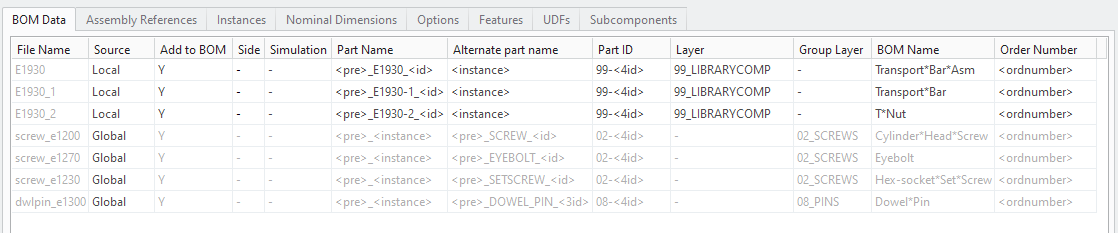
 - Define the BOM data for this component. Use Local source for the assembly specific components. Use the global part name entries for the standard EMX components.
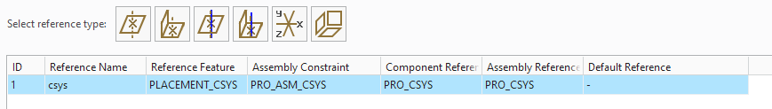
- Got to the tab Assembly references.
- Set up PLACEMENT_CSYS as assembly reference
- Got to the tab UDFs.
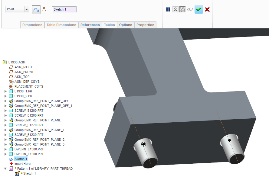
- Create Threads and Quilt Faces in the bottom area of the Cuts and Threads tab.
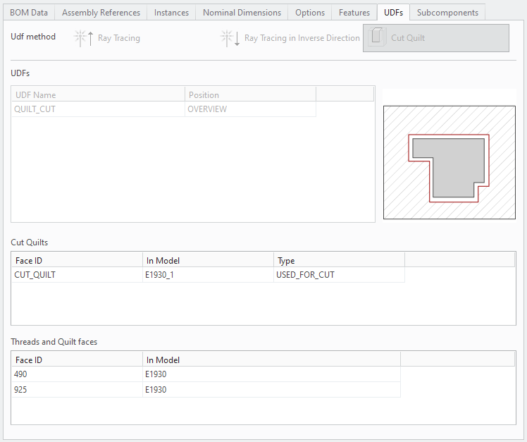
- Select the Threads and Quilt Faces table and click Add row
 from the Right-Mouse menu. You are prompted to select an Axis and Surface.
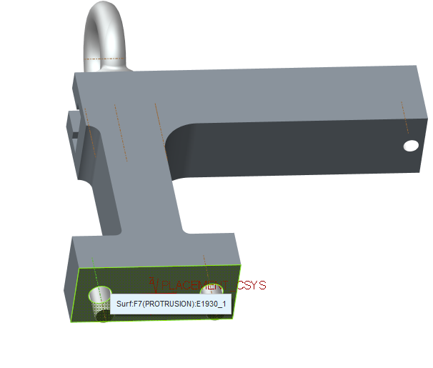 A Predefined Thread UDF will be assembled to the assembly.
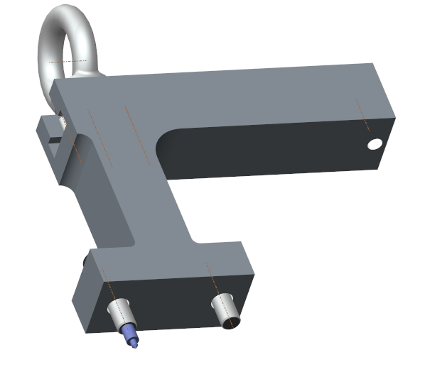
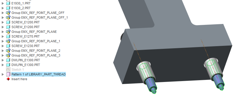
- Pattern this UDF by creating a Sketch which contains 2 datum points directly in the center of the two bores.
- Create a pattern of the Predefined Thread UDF.
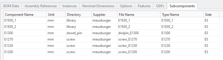
- Switch to the Subcomponents tab.The columns Supplier and Directory need to be adapted. The library assembly needs to know where the component data for subcomponent comes from.The components E1930_1 and E1930_2 can be found in the Directory library.The Supplier is meusburgerAll other components can be found in the regular components folders.The dowel pin E1300 is found in Directory dowel_pin with a Supplier meusburger.The screws E1200, E1270 and E1230 are found in Directory screw with a Supplier meusburger.
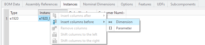
- Go to the Instances tab.Select the column Instances and click
 Insert columns before
  Dimensions from the Right-Mouse menu to add a set of instance dimensions to the table.
 A dialog box opens which list all defined dimensions symbols of the assembly model.Select THREAD_DIAMETER, CORE_LENGTH, POINT_ANGLE, CORE_DIAMETER and THREAD_LG from the list and confirm with OK. The instance dimensions are added to the table.These five dimensions can be used to alternate the predefined thread for different instances of the assembly.
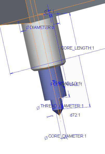
- Select the column Instances and click Insert columns before
 Subcomponents from the Right-Mouse menu to add a set of subcomponents as instance dimensions to the table.A dialog box opens which list all defined subcomponent names of the assembly model.Select E1930_1, E1930_2, E1300, E1270, E1230 and E1200 from the list and confirm with OK. The instance dimensions are added to the table.These 6 subcomponent instance dimensions can be used the alternate the subcomponent of the assembly.
 - Add four additional rows to the Instances table. The biggest job now is now to set up all dimension and subcomponent values correctly.Dimension values need to be typed in manually. The valid subcomponent instances can be selected from a pull-down menu.

- Switch to the Nominal Dimension tab.As nominal value select the subcomponent E1930_1 and make it a PULLDOWN Type
- Save the assembly with
 .As a result you will find the E1930.dat file and the picture E1930.png in <library_emx>/tutorial folder.
Assemble the New Library Assembly E1930
If everything is set up properly you can now assemble the new Library Component. Use the already provided E1930 from the library/meusburger folder as a comparison reference.
- Open the mold base TUTORIAL.ASM
- Add a coordinate system to the mold base with the appropriate orientation.
- Select
 .
.
- Select the directory meusburger from the directory tree list.
- Double-click e1930 .
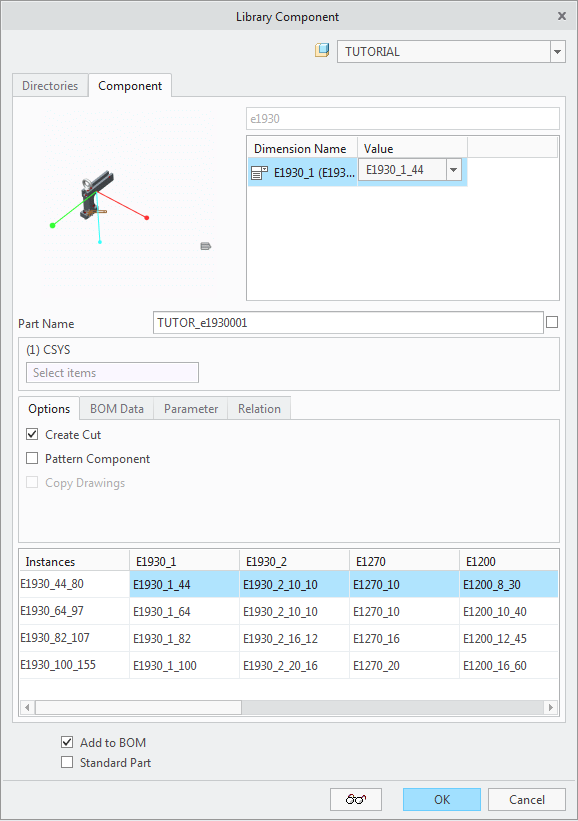
- Select on of the 4 available instances and leave the dialog with OK.As a result you will find the Assembly Component add to the mold base.
Background Information
When working with complex library components they might have several independent cut quilts and generate a huge amount of
individual cuts in plates or other models. During the redefine of such library components you might face problems with the
cut generation. If you set the EMX Option UPDATE_CUTS_IN_REDEFINE to YES, you force EMX to simply remove previous cuts and generate new ones.