To Add a Part to the Library
Download 00_library_part to start with this chapter.
Load the new library component
- Erase all models from the Creo session.
- Copy the file E1920.PRT from <install_tutorial>/models/library_prt into an new folder<install_emx90>/components/mm/library/tutorial.
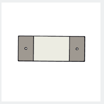
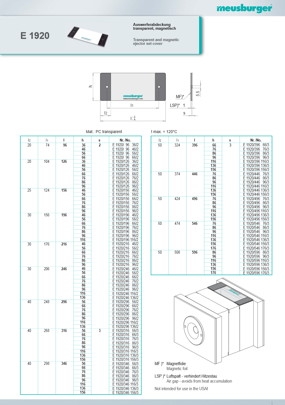
- Open the model E1920.PRT from this directory.
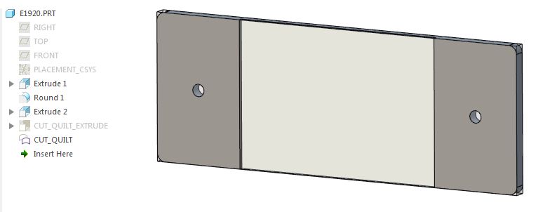
Create an Image and Define the Component BOM Data
- Start
 .The Component Editor dialog box opens.
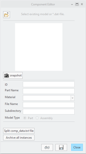
- Click Open model or *.dat fileThe File Open dialog box appears. Select e1920.prt from current working directory. The dialog is filled with default library component information.
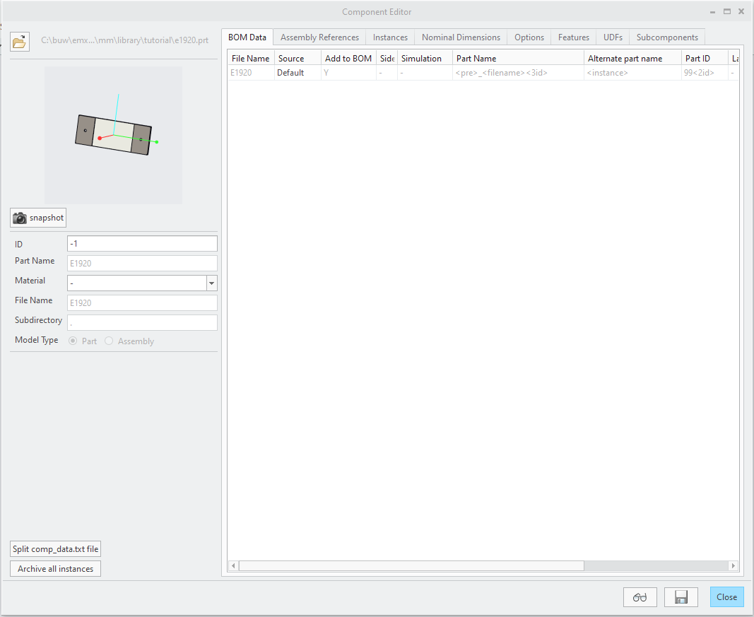
- Adjust the model orientation and click
 Snapshot Define the BOM data for this component.Global entries of the part name dat that can be found for regular EMX components in the sheet.
- In the Source cell select Local. The part name rule will be written into the EMX_BOM_INFO section of the dat file directly and applied with highest priority.
- Set Add in BOM to Y so this component will be displayed in the bill-of-materials later.
- Enter the Part name <pre>_E1920_<id>.
- Enter the Alternate part name <instance>.
- Keep Part ID as 99<2id>.
- Keep BOM Name as <instance>.
- As target Layer enter 99_LIBRARYCOMP. The component will be place on this layer after the assembling process.
- Enter Group Layer -.
- Enter BOM Name Magnetic*ejector*set*cover. The Asterisk is used as a placeholder for spaces
- Keep Order Number as <ordnumber>.
Define the Assembly References
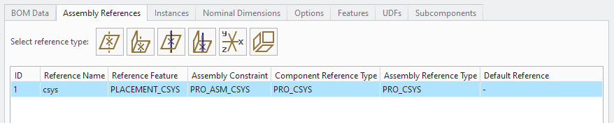
- Click the tab Assembly References.
- Click
 and select the coordinate system PLACEMENT_CSYS from the model E1920.PRT.A new line appears in the assembly constraints.
 - Select this line (with ID1) and edit the entry for Reference Name in the edit area under the list to CSYS.
Define the Instances
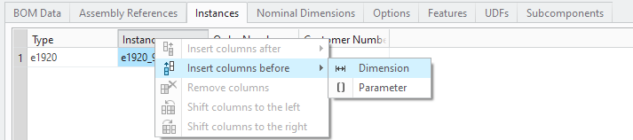
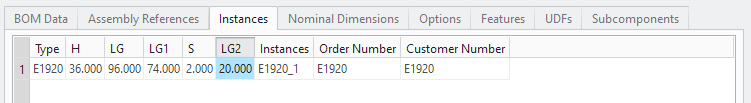
- Click the tab Instances.In the table all instances that are defined for the library component can be seen.By default only one instance with the current model values is added to the table.In the initial step all instance dimensions need to be defined I the table
- Select the column Instances and click
 Insert columns before
  Dimensions from the Right-Mouse menu to add a set of instance dimensions to the table.
 A dialog box opens which list all defined dimensions symbols of the part model. Select S, H, LG, LG1 and LG2 from the list and confirm with OK. The instance dimensions are added to the table.
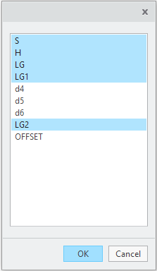 Use
Use Shift columns to the left and
  Shift columns to the right to change the order in the table.
- There are now two different ways to edited the isntances rows.
- Select the rows and use
 Insert rows below and
  Insert rows above to add additional rows. Use Double-Click to edit the cell values
 - Use the Copy-Paste tools and edit the instances in Excel
In this tutorial the focus is on the second option. - Select the rows and use
- Click Copy
 to copy the current content of the table.
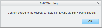
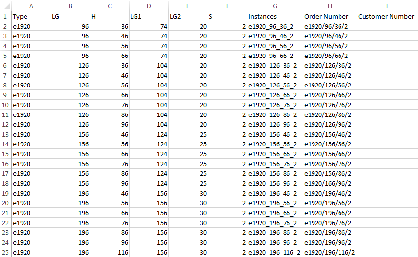
- Open an MS Excel instance and paste the content to the Excel-Sheet.
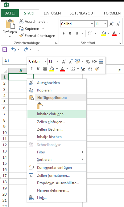 All rows will be displayed in the Excel-Sheet.
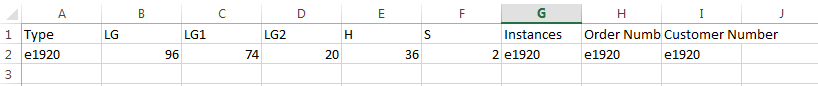
- Enter instances that can be found in the Meusburger Digital catalog.
- Copy the final instance sheet to the EMX instances list with Paste

Define the Nominal Dimensions
- Click the tab Nominal Dimensions.
- Select the table and click Insert rows below from the Right-Mouse menu.A dialog box opens which list all instance dimension which were defined in the instances table. A nominal dimension can only be defined in case it is a valid instance dimension.
- Select the dimensions LG and H from the list Click OK to confirm the selection. Two new lines appear in the Nominal Dimension list.Use
 Shift rows up and
  Shift rows down to change the order in the table.
- Select the LG line and overwrite the Dimension Name (symbol LG) with length
- Select the H line and overwrite the Dimension Name (symbol H) with height.
Define cutout UDFs
- Click the tab UDFs .For library components the UDF QUILT_CUT is used by default.
- Select the table Cut Quilts and click
 Add row from the Right-Mouse menu. The Selection menu appears.Select the Quilt feature CUT_QUILT in the E1920.PRT.
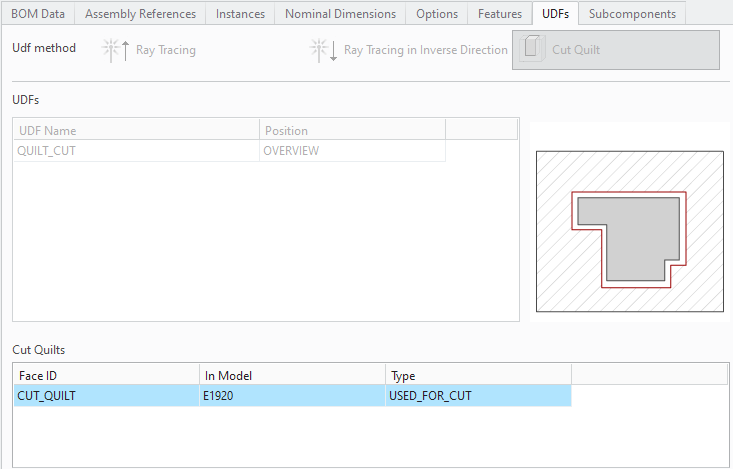 No Predefined threads should be defined for this example.
Save the Library Component
- Click
 EMX will create a e1920.dat file and a e1920.gif-file in the directory where the library part is located. The model will also be saved again as e1920.prt.1. Delete the original file e1920.prt and rename the new file without an index. This step is not required, but it helps you to keep the library folders clean.
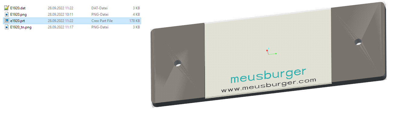 The component is now fully defined.
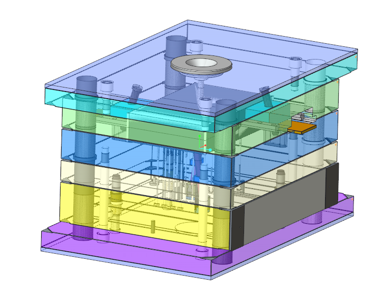
Assemble the component
- Open the mold base TUTORIAL.ASM
- Create a coordinate system as assembly reference for the plate as shown in the picture below.
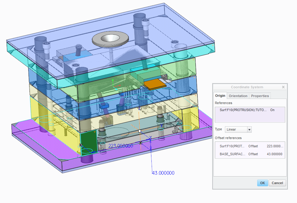
- Make sure that the orientation of the coordinate system is correct. X-Vector is normal to surface and Z-Vector points into opening direction of the mold base.
- Select
 .
.
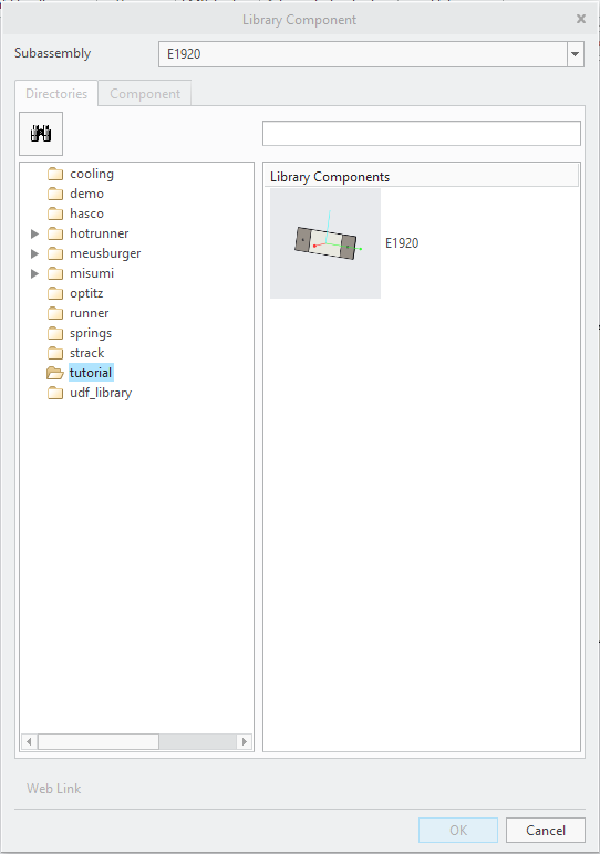
- Select the directory meusburger from the directory tree.
- Select part e1920 with Double-Click.
- Set the Length (LG) value to 446.
- Set the Height (H) value to 86.
- As assembly reference (1) CSYS select the recently created coordinate system.
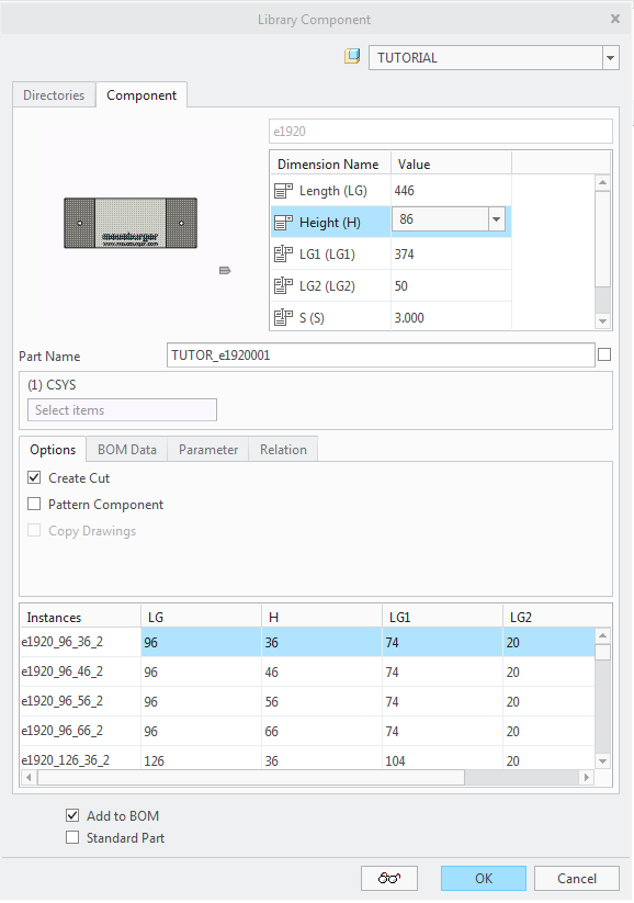
- Leave the Library Component dialog with OK .