Preparing Creo symbols
Creo Symbol preparation
- Define your symbols in a 2D drawing. (Make sure you create your symbols in the lowest Creo version that you want to support.)
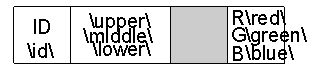
- Use to open the symbol definition mode.Your symbols may contain any kind of graphical entities such as lines or polygons and text notes. Note texts or rather “prompts” having a leading and trailing backslash are interpreted as a ‘Variable texts’ by Creo. Variable texts in the Creo Symbol will automatically be listed in the Symbol def dialog.Your created symbol may look like the following:These texts will be filled at runtime whit the defined contents, specified in the Symbol Def object.
Understanding the placement of the legend symbols within the Creo graphics area
- The size of the Creo graphics area is always 843 by 1000 ‘graphic area’ pixels. That applies no matter what monitor resolution
you are using.
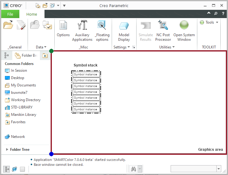
- SmartMBDTools creates legend symbols for each displayed color within the active Combined state. These symbols are combined to the symbol
stack. The stack is generated either from top left corner (green bullet) down or from bottom left corner (blue bullet) up.
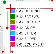
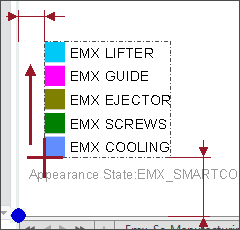 Top left to bottom left
Bottom left to top left The size of the single symbol instances depend on the monitor resolution and the original size of the Creo symbol.The values for the offset distances and the behaviour for the stack has to be configured in the supporting object ‘3D Position’