To Define Parameters
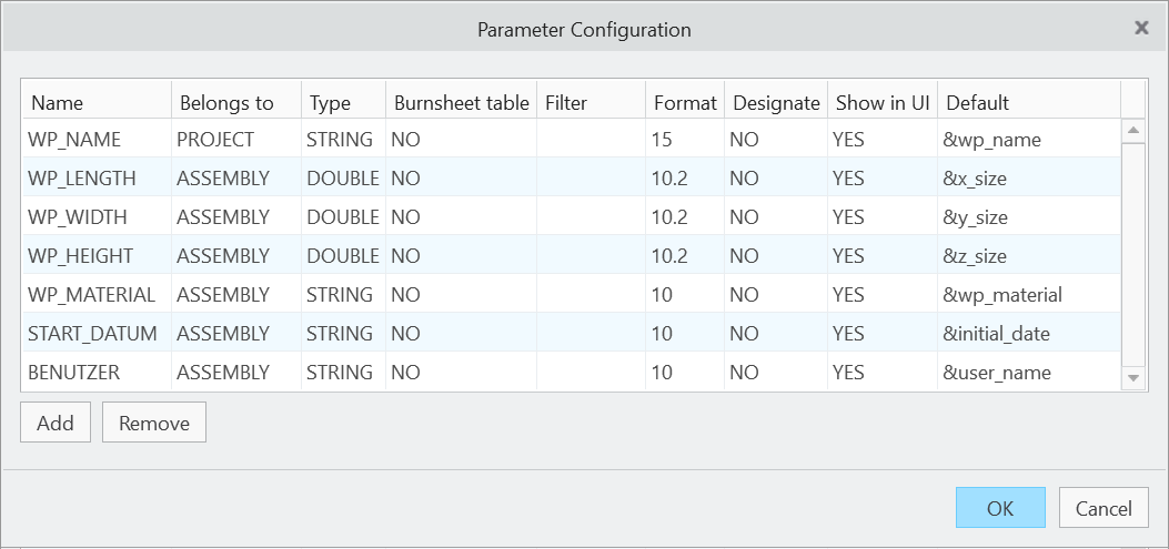
Click Project  Edit Parameters. The Parameter dialog box opens.
- Enter Name in 1st column.
- Enter Belongs to in 2nd column. Belongs to describes the owner of the parameter. Following values are valid:
- PROJECTParameter saved to assembly and electrodes. Value saved at assembly automatically sets electrode parameter unless it’s unlocked.
- ASSEMBLYParameter saved to assembly.
- PARTParameter saved to electrode part. For values that are the same for all positions of the electrode model.
- COMPONENTParameter saved to component feature in assembly. For values that differ from position to position.
- COREParameter saved to workpiece component.
- PROJECT
- Enter Type in 3rd column. Following values are valid:
- Integer
- String
- Double
- Boolean
- Enter Burnsheet Table visibility in 4th column. This controls the visibility of parameters in assembly drawing tables and Burnsheet UI.
- Enter associated Filter in 5th column. Available filters can be used in Properties UI and Base UI. Any custom filter can be added or set by changing the value. Default filter:
- All Shows all parameters defined for object.
- Default Shows all parameters set visible in column Show GUI.
- Position Shows all parameters representing a position or angle.
- Technology Shows all parameters that are specific settings for EDM.
- Enter Format in 6th column to set the parameter format. This print-format defines the column width and number of decimal places in drawing tables and export. Enter one number for STRING- and INTEGER-parameters or two numbers separated with "." for DOUBLE.For example use 8.3 to set the column width to 8 and the number of decimal places to 3.
- Enter Designate in 7th column to set or unset designation for PDMLink.
- Enter Show GUI in 8th column to control visibility of parameters in Properties dialog box.
- Enter Default in 9th column. This can be:
- A fixed value for STRING, INTEGER or DOUBLE-parameters.
- A value from a selection list. Open <configuration directory>/sel_list.txt to add or edit a list for a parameter. List begins with #<parameter name> and is followed by the values, which are specified line by line. In this case the user can only select one of this values when modifying the parameter in the electrode dialog box or the burn sheet dialog box.
- Default rule. The defaults provide access to values calculated by SMARTElectrode. All this internal values are identified by a "&". The list of available internal rules can be found below.
Click  Add to insert a copy of selected parameter below.
Add to insert a copy of selected parameter below.
Click  Remove to remove selected parameter from list.
Remove to remove selected parameter from list.
Click  Up to move selected parameter upwards.
Click  Down to move selected parameter downwards.
Click OK to save changes to configuration.
Click Cancel to discard changes and close UI.
List of Parameter Defaults
- &<parameter name> To reuse any parameter add “&” to the parameter name and set this as default. SMARTElectrode tries to find the parameter inside the main assembly, the electrode part and the electrode component.
- <fixed value>Input any value that should be assigned to the parameter.
- &inheritRead the value from a parameter with the same name from parent. Assemblies get the value from selection list or original ref-part. Cores inherit from original ref-part. Electrodes inherit from assembly.
- &projectidProject name. Used to set a superior project name that differs from assembly name.
- &projectdirShows the absolute path of the assembly.
- &electrode_countNumber of unique electrode models in assembly.
- &position_countNumber of active electrode positions in assembly.
- &lockedMake a parameter known to SMARTElectrode.
- &partnamePartname of the electrode.
- &qtyQuantity of identical models in the assembly.
- &idUnique SMARTElectrode-id.
- &seqIndex of electrode position.
- &x_pos:<feature_name>X-position of the electrode. To get X position of any named coordinate system inside electrode (for example STARTPOS or SECUREPOS) with respect to the operation origin.Electrode zero is with respect to operation zero is used without definition of a feature name.
- &y_pos:<feature_name>Y-position of the electrode. To get Y position of any named coordinate system inside operation or electrode (for example STARTPOS or SECUREPOS) with respect to the operation origin. Electrode zero is with respect to operation zero is used without definition of a feature name.
- &z_pos:<feature_name>Z-position of the electrode. Z-position of the electrode. To get Z position of any named coordinate system inside operation or electrode (for example STARTPOS or SECUREPOS) with respect to the operation origin.Electrode zero is with respect to operation zero is used without definition of a feature name.
- &x_angleRotation about x-axis
- &y_angleRotation about y-axis
- &z_angleRotation about z-axis
- &x_dist:<feature_name>To get X distance of any named coordinate system to another coordinate system based on operation origin. Electrode zero is with respect to operation zero is used without definition of a feature name.
- &xy_dist:<feature_name>To calculate distance from start position to electrode's end position in XY-plane of operation. This parameter can be used to ouput the length of the vector for lateral machinings.Electrode zero is with respect to operation zero is used without definition of a feature name.
- &y_dist:<feature_name>To get X distance of any named coordinate system to another coordinate system based on operation origin.Electrode zero is with respect to operation zero is used without definition of a feature name.
- &z_dist:<feature_name>To get X distance of any named coordinate system to another coordinate system based on operation origin.Electrode zero is with respect to operation zero is used without definition of a feature name.
- &materialMaterial that was selected in definition dialog box
- &supplierSupplier of electrode blank.
- &typeType of electrode blank. Rectangular, cylindric, ...
- &instanceSelected size from list. This value is not changed even if dimensions are edited in Electrode > Modify.
- &sizeSize (max. bounding box) of the electrode.
- &x_sizeX-dimension of the electrode.
- &y_sizeY-dimension of the electrode.
- &z_sizeZ-dimension of the electrode. Reads electrode’s blank length defined by datum plane “LENGTH”.
- &z_size_solidShows the overall length of electrode geometry.
- &blank_areaCross section area of electrode blank.
- &holdernameName of the holder that is placed on an electrode.
- &processorKind of erode-processor to be used for manufacturing, i.e. AGIE, FANUK.
- &orbitType of orbit, i.e. linear, rectangular...
- &overburn1First overburn-value.
- &overburn2Second overburn-value.
- &overburn3Third overburn-value.
- &overburn4Fourth overburn-value.
- &overburn1_qtyNumber of steps/electrodes for roughing.
- &overburn2_qtyNumber of steps/electrodes for semi-finishing.
- &overburn3_qtyNumber of steps/electrodes for finishing.
- &overburn4_qtyNumber of steps/electrodes for fine-finishing/polishing.
- &burnareaTotal area of all faces in the burning face quilt.
- &burnarea_xyEffective burn-area. This is the projected area of the contact surfaces in z-direction.
- &burnarea_maxMaximum side projection of the burning face quilt.
- &burnarea_max_angleZ-angle where this maximum projection can be found.
- &burnarea_minMinimum side projection of the burning face quilt.
- &burnarea_min_angleZ-angle where this minimum projection can be found.
- ¤t_dateCurrent date. Date format is defined by option DATE_FORMAT.
- &initial_dateDate of creation. Date format is defined by option DATE_FORMAT.
- &user_nameUser name of designer.
- &locationShows the absolute path of the electrode.
- &surf_classQuality standard (Ra, VDI, Rz, ...).
- &surf_qualitySurface quality.
- &priorityPriority of machining. Control specific selection list of values.
- &machining_dirTo output direction of machining. The vector from start position to end position are used for calculation. Current values are: +X, -X, +Y, -Y, +Z, -Z. The default is -Z. A 3d-Vector will be showed as combination of values. Example: -X-Z.
- &core_materialWorkpiece material.
- &core_nameExtract name electrode is placed on.
- &core_lengthOverall length of workpieces.
- &core_widthOverall width of workpieces.
- &core_heightOverall height of workpieces.
- &assembly_nameName of electrode assembly.
- &operation_nameName of operation subassembly.
- &operation_idId of operation.
- &qm_...Parameters carrying additional information for quality measuring:
- &qm_tol_minAllowed lower tolerance for quality measuring.
- &qm_tol_maxAllowed upper tolerance for quality measuring.
- &qm_stylusStylus name for measuring.
- &qm_tipTip name for measuring.
- &qm_prehitPrehit distance during measuring.
- &qm_retractRetract distance during measuring.
- &qm_preset_stylusStylus name for preset.
- &qm_preset_tipTip name for preset.
- &qm_preset_prehitPrehit distance during preset.
- &qm_preset_retractRetract distance during preset.
- &qm_tol_min