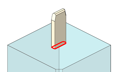
To Add Base
A base for current solid is necessary to finish electrode design. Use the commands as follows:
- Click Electrode
 Base to create a base group. The Base dialog box opens.
 - SMARTElectrode adds a base using options DEFAULT_SUPPLIER and DEFAULT_TYPE if no base is attached to the electrode.
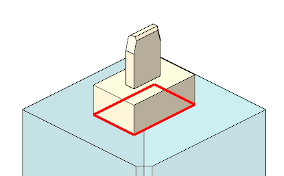
- Adjust values for base position:
- Enter Position X, Y, Z of base.
- Enter Rotation A, B, C of base.
- Select different Blank Type if necessary.
- Select different Blank Size if necessary.SMARTElectrode looks for a suitable blank size in the list of available instances automatically.
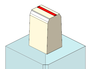
 Unlock blank dimensions to adjust values:
- Enter Blank A_Base to set X-size of blank.
- Enter Blank B_Base to set Y-size of blank.
- Enter Length to set blank height.
- Enter D1 to set Z-offset from blank FREE_FACE to workpiece solid.
- Enter Blank D2 to set base height.
- Enter D3 to set Z-offset from electrode top to blank length.
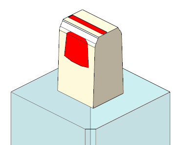
- Detailing Chamfer 1
- Set/unset Chamfer 1 to resume or suppress chamfer 1 (-X/-Y direction).
- Enter Value of chamfer 1.
- Detailing Chamfer 2
- Set/unset Chamfer 2 to resume or suppress chamfer 2 (-X/+Y direction).
- Enter Value of chamfer 2.
- Detailing Frame
- Set/unset Frame to resume or suppress frame feature.
- Enter Frame height.
- Enter Frame width.
- Select positions of Origins:
- Electrode Origin
- CAM Origin
- Switch to 2nd tab Details to define:
- Technology
- Open Burn-Area to calculate effective burnarea
 Fast Calculation to calculate effective burn-area by electrode contour only
 Exact Calculation to calculate effective burn-area with comparison to workpieces
- Undersize
- Electrode Holder
- Click OK.