Placing Stack Notes
The Stack Notes  tab provides a selection UI for all Stack Note definitions that are associated with the current context node.
The complete tab can be hidden via a configuration setting if you do not want to use this functionality.
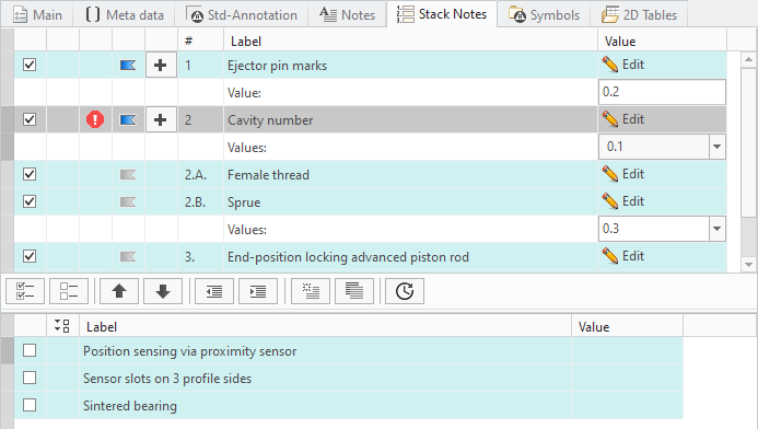
- The display is split into two areas.
- Pool area (Lower display) — Available entries associated with the filter node are listed here
- You may expand
 or collapse
  the value rows and column to improve the visibility
- You may expand
- Collection area (Upper display) — All selected items and its values are displayed here
- Pool area (Lower display) — Available entries associated with the filter node are listed here
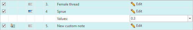
- The Label column indicates the Stack Notes label. It may not be equal with the containing text. When you move the mouse over the text label, a tooltip with the complete text will appear.
- The Value column is for entering values or choosing from pull-down lists.
- The # (Number) column applies an automatic numbering scheme. You can deactivate numbering using the configuration option NOTE_LISTING_TYPE.There are several more options to control the formatting of Stack Notes. Please see the Configuration Chapter for more details.
- The Flag column indicates whether an entry is marked as flagged. Find more information here.
- The Flag Placement column provides the Plus
 button to place one or multiple flags for the selected row. It only appears when the flag is set to active.
 - The Flag Status column shows a warning notification symbol, if no flags have been placed for an active flag symbol.
Selection
- Select entries from the Pool area one by one or all
 .
.- The selected notes are displayed in the Collection area.
- You can sort the entries with the

 buttons.
- One entry may contain multiple rows. A headline and several value or choice rows. The complete entry is marked with a dark bar when selected.
- (Optional) Enter a value or chose from a pull-down list if necessary.
Placement
- Use the Plus to start placing the notes.
- The SMARTAnnotate dialog will disappear and the notes stack will stick to your cursor for placement.
- Click LMB to drop the stack
- Move your mouse over the notes stack.
- Watch more and more notes appear as you hover down the stack.
- All notes will appear immediately if you move the mouse over the top of the stack.
- Use LMB again to drop those notes that are currently displayed.
- The stack will break at this point and allows you to continue with the next column the same way until all notes are dropped.
- A horizontal snap line will help aligning the columns will placing the notes.
- The placement finishes automatically when all notes are dropped.
- The SMARTAnnotate dialog will re-open automatically.
- The selected notes will remain in the Collection area.
(Optional) Flag Activation and Placement
- Click on the little flag symbol to activate the Flag indication
 — Flag inactive
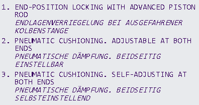
 — Flag active
- The note number will be marked as flagged within the note text in the model/drawing.
- The note number will be marked as flagged within the note text in the model/drawing.
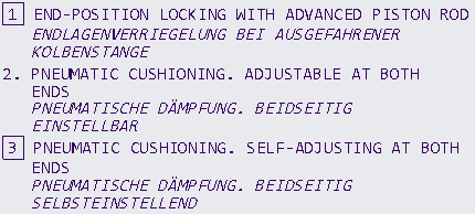
 — Flag indication (option LISTING_FLAG_ENABLES_MIXED_STATE = YES)
- Same as active state, except that no warning notification will be shown if there was no flag note placed yet within the model/drawing.
- Use the Plus in the respective row to start placing the flag.
- The SMARTAnnotate dialog will disappear and the Settings dashboard within the ribbon is shown.
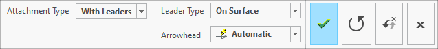
- The SMARTAnnotate dialog will disappear and the Settings dashboard within the ribbon is shown.
- Chose the Attachment Type from the pull-down menu.
- Free — Unattached placement
- At vertex — Select a vertex
- Normal to entity — Placement normal to selected geometry
- With Leaders — Select one or multiple attachment points
- On Entity — Select a geometry item that the note will placed on
- Offset — Select a 2D item and chose an offset from there.
- Chose the Leader Type from the pull-down menu
- Chose the Arrowhead style from the pull-down menu
- Select the attachment references (if required) and place with LMB.
- Select OK from the little popup menu or use MMB to finish the placement.
- Finish the placement
- Select Redo
 from the dashboard UI to redo the current placement.
 - Select Repeat
 from the dashboard to keep the current instance and add another one.
 - Select OK
 from the dashboard UI or MMB to finalize the placement.
- The SMARTAnnotate dialog will re-open automatically and you can continue with another flag placement.
- Select Cancel
 from the dashboard UI to discard the placement.
- The SMARTAnnotate dialog will re-open automatically and you can continue with another flag placement.
- Select Redo
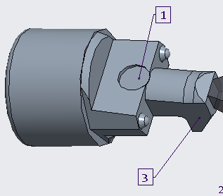
The created flags may look like this:
In 3D mode, the user-placed flags will be stored as elements within an annotation feature. The following parameters are created
for these elements:
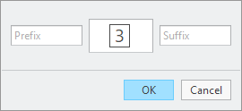
The prefix and suffix text can be changed using the edit function  . After a flag note was selected, the following dialog will appear:
- FLAG_NOTE: Value is the name of the annotation element that corresponds to the note within the stack with the same number which the flag is referencing.
- BUW_FLAG_TEXT: Value is the actual number for instance “1” or “3”.
- BUW_PREFIX: This parameter gets called-out within the flag note text. If its value is non-empty, the value text is shown in front of the flag text.
- BUW_SUFFIX: This parameter gets called-out within the flag note text. If its value is non-empty, the value text is shown behind the flag text.
. After a flag note was selected, the following dialog will appear:
If the configuration option ENABLE_FLAG_NOTE_PROTECTION is set to NO, then the flag notes can also be edited interactively.
On the one hand, the annotation element parameters can be changed by opening the corresponding Creo parameters dialog. On
the other hand, the note text can be selected and by double-clicking on the parameter call-outs, Creo shows an input panel
that allows to edit the parameter values as well.
‘Custom Notes’ for individual user modifications
Custom Notes are a possibility for the user to add individual notes to the stack. This adds a lot of flexibility and individualism to
this kind of note type, but also has its limitations.
- Custom Notes do not support automatic translation
- Converting an existing Stack Note entry into a Custom Note is a point of no return
- No support for drop-down menus or Input fields.
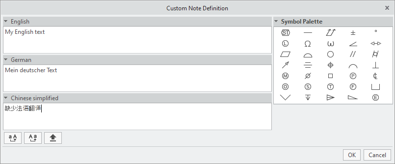
Custom notes can be created in single or multi language manner in respect to the corresponding configuration setting. In single
language mode, there’s just one text area for text input while in multi language mode, there’s a text area for every language
that was selected. For instance if three languages are chosen, the dialog will appear like this:
The following illustrations will show the custom note dialog used in single language mode.
There are different options to create a Custom Note that you can turn on or off individually through the configuration.

- Create from scratch
- Select
 from the icon bar within the Stack Notes tab
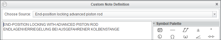
- The Custom Note Definition dialog opens
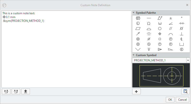
- The Custom Note Definition dialog opens
- Enter any text into the large text area. You will have to enter your own translations here, if intended. Use the following
buttons to control your input.
 — Converts all selected characters to Upper Case
 — Converts all selected characters to Lower Case
 — Caps lock key
- (Optional) Select a symbol from the symbol palette.
- (Optional) Select a custom symbol to be called out within the text from the drop-down list.
- Click OK and the new Custom Note
 will be added to notes stack.
- Select
- Create by copying an existing note entry
- Select
 from the icon bar within the Stack Notes tab
- The Custom Note Definition dialog opens
- The Custom Note Definition dialog opens
- Choose an existing notes entry from the drop-down list. The original text appears within the text area.
- Modify the existing text as you like
- Click OK and the new Custom Note will be added to notes stack.
- Select
- Create by selecting an existing text from the drawing or model
- Use option CUSTOM_NOTES_CHOP_RULE to define a regular expression that will cause the selected note to be split up into separate notes at each occurrence of specific characters.
- Select
 from the icon bar within the Stack Notes tab
- The Custom Note Definition dialog opens
- Modify the existing text as you like
- Click OK and the new Custom Note will be added to notes stack.
- Create by importing from a CSV file
- Use option CUSTOM_NOTES_CHOP_RULE_CSV to define a regular expression that will split up the text from CSV file into separate notes at each occurrence of specific characters.
- Select CSV from the icon bar within the Stack Notes tab
- The File Open dialog opens
- Select the intended CSV file from your folder structure
- The content gets loaded into the Custom Note Definition dialog
- According to the definition within your Configuration, the content is split into separate entities that you can walk through with the little arrows at the bottom.
- Modify the existing text of each entity as you like
- Click OK and the new Custom Notes will be added to notes stack.
- Use the Recent
 button to load the custom notes from your local ‘recent notes’ stack.
 - Define the character width of the stack notes column.
- Use the Width
 button to define the width of the stack
- A dialog opens to enter an integer value for the maximum characters in a row of the stack.
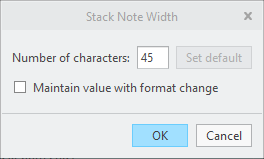
- Check the box to maintain the width even in the event of a format change.
- A dialog opens to enter an integer value for the maximum characters in a row of the stack.
- Use the Width
- Edit an existing note entry
- Select Edit from within the existing line item in the list
- You will be prompted if you really want to convert this entity into a Custom Note.
- The Custom Note Definition dialog opens showing the original text.
- Modify the existing text as you like
- Click OK and the existing note will turn into a Custom Note .
- Select Edit