To Work with Drawing Support Features
Add a format to all plate drawing templates
Beside the BOM the drawing is still one of the most important sources of information for mold manufacturing. EMX offers drawing
templates for almost all template models. They are located in the installation directory of EMX.
Beside the assembly drawing that is created when creating/modifying an EMX project, additional drawings might be required
for individual components such as plates, ejector pins, etc. EMX provides drawing-templates for most EMX components. They
are located in the <install_emx>/components/mm/<comptype> folder.
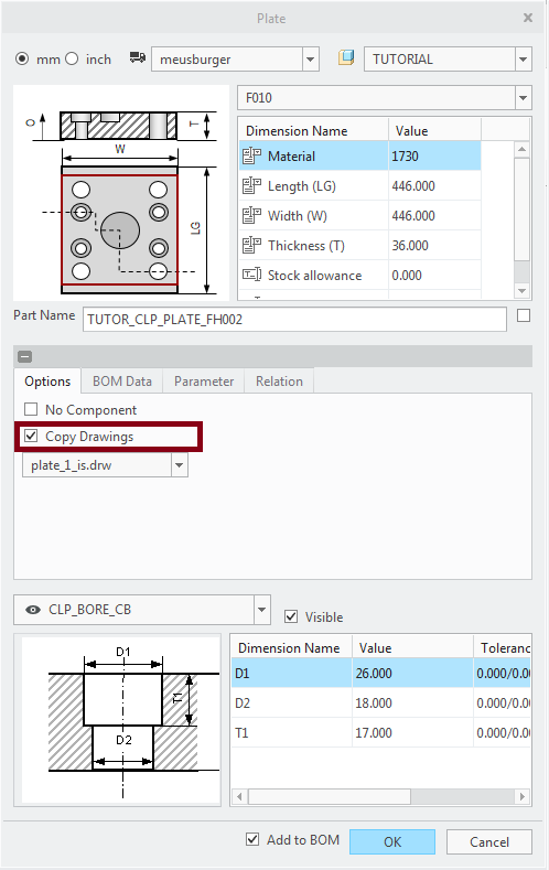
In the Plate dialog box, the check button to copy the drawing is activated by default. All drawings that have the plate-template name
included are listed in the drawing pull-down.
The available plate types (with ES for moving half and IS for fix half) are:
| plate_1 | Clamping plate |
| plate_2 | Corepin Retainer Plate |
| plate_3 | Support Plate |
| plate_4 / plate_4_left | Rail (one or two models) |
| plate_5 | Cavity Plate |
| plate_6 | Ejector Retainer Plate |
| plate_7 | Ejector Base Plate |
| plate_8 | Stripper Plate |
- Add your drawing formats to this templates BEFORE starting your design. Use the function to support this task.If you want to use EMX drawings it is recommended to set the EMX Option SAVE_DRAWINGS to YES. It is not possible to create a plate drawing later, if you forgot it during the initial plate definition.For other EMX components, you can decide wether the check button Copy Drawing in the Component dialog box is set or not in the EMX Option EMX_CHECK_DWG_TYPES. Simply list the component types for which the checkbutton should be active, the default is ejector|slider|lifter|latchlock.
- Use the option SET_EMX_DTL to decide wether the dtl-settings from file <install_emx>/configuration/symbols_dtl/<unit>/emx.dtl should be applied to a drawing or not.
Quick Access to drawings when working in assembly mode
- Select
 to open the drawing from the current working directory or from session directly.
 - Select a component with LMB. If a drawing with the same name exists, it will be opened.
Balloon placement with EMX
- Open the assembly TUTORIAL.ASM.Use
 to open the drawing from session directly.
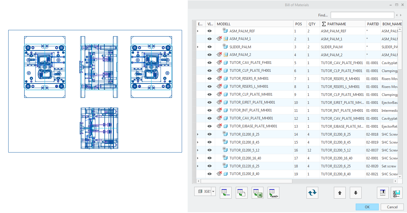
- Select Bill of Materials
 to open the EMX Bill of Materials dialog box. A symbol in the table indicates wether the balloon for a component exists
 or not
  .
.
- Click RMB on this symbol in the line of TUTOR_INT_PLATE_MH001 and Select Add BOM Number.The model is highlighted in all views of the current sheet and the Bill of Materials is hidden.
- Click with LMB the position of the arrow end (LMB 1)and click again for the balloon position (LMB 2).
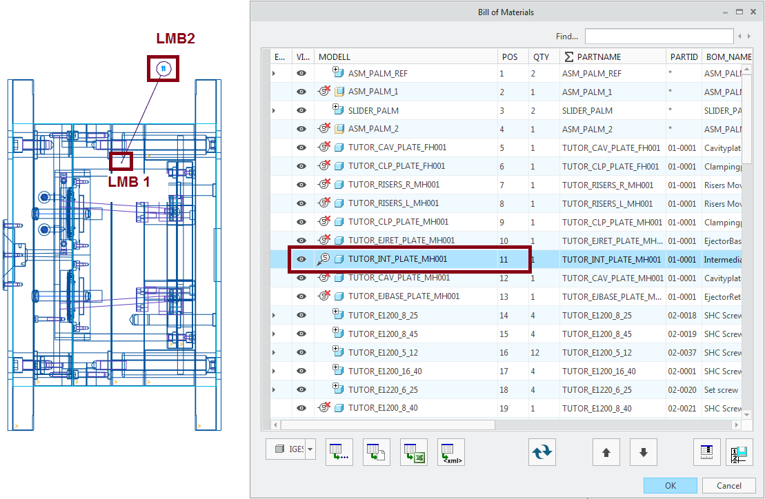
- Click RMB again on the symbol again in the BOM table and remove the balloon again with Remove BOM Number .
Balloon placement with Creo
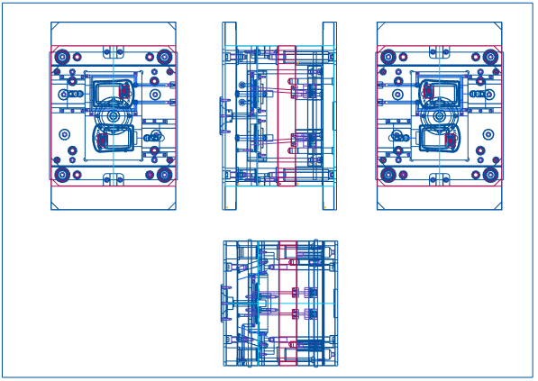
Creo offers a flexible way to place balloons. Based on the BOM-Table with repeat region on sheet 3 of the EMX assembly drawing
the balloons can be placed with .
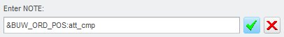
It is possible to define the content in the balloon rather flexible. The easiest way is to use the Component Parameter BUW_ORD_POS
in the balloon note.
Background Information
The symbols and their diameter-table are located in <install_emx>/configuration/symbols_dtl/<unit> . In ejpin_symbols.cfg the nominal diameter for ejector pins and their related symbol is listed. With option SUPPRESS_EJP_NOTE set to YES the display of the extra note can be avoided.