To Create a Slider
Download 44 To Create a Slider to start from with this chapter.
Assemble a Slider
In this tutorial a slider will be designed to create the two snap connection at the top of the plastic part ARTICLE_REF.PRT.
The cavity assembly MFG_1.ASM already contains a slider part MOLD_VOL_SLIDER_1.PRT which contains the contour geometry that needs to be moved sideways to prevent damage from plastic part during the ejection
process.
- Open the mold base TUTORIAL.ASM.
- Select EMX Components Components
 Slider.
- Select the TUTOR_SHARED from the Subassembly pull-down menu.
- Select strack from the Supplier pull-down menu.
- Select Z4294L from the Type pull-down menu.
- Select 1 from the TYPE_selector in the Nominal Values table.
- Define the references.
- Click (1) Csys and select the CSYS_SLIDER coordinate system in the ARTICLE_REF.PRT.
- Make sure that the option Remove tangent radii is enabled.
- Enable the Option Pattern for all models.
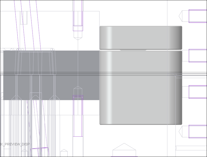
- Assemble the slider with Preview

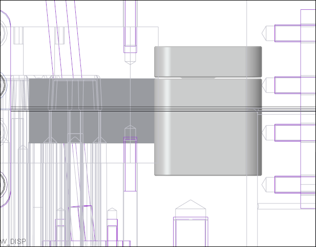
- Measure the distance between the cavity insert side surface and the slider guide body.The measured distance is 1.92237 mm.
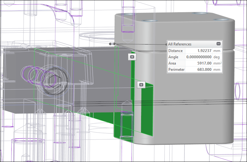
- Set the OFFSET_X value to the recently 1.92237 mm to make sure the sliders is flush to the cavity insert part.
- Assemble the slider again with Preview
- Finally assemble the sliders with OK. Two sliders are assembled and cuts are created to the interfering parts.
Finish the Slider Design
The cut quilt surface of the slider assembly was interfering with the MOLD_VOL_SLIDER_1.PRT part. Therefore a Solidify group was created in MOLD_VOL_SLIDER_1.PRT.
- Delete the group QUILT_CUT in MOLD_VOL_SLIDER_1.PRT.
The geometry of the slider part MOLD_VOL_SLIDER_1.PRT need to be added to the newly created slider cam TUTOR_S_CAM_3001.PRT.
- Activate the TUTOR_S_CAM_3001.PRT within the new slider assembly.
- Create a assembly depended Copy Geometry feature of all solid surfaces of the MOLD_VOL_SLIDER_1.PRT
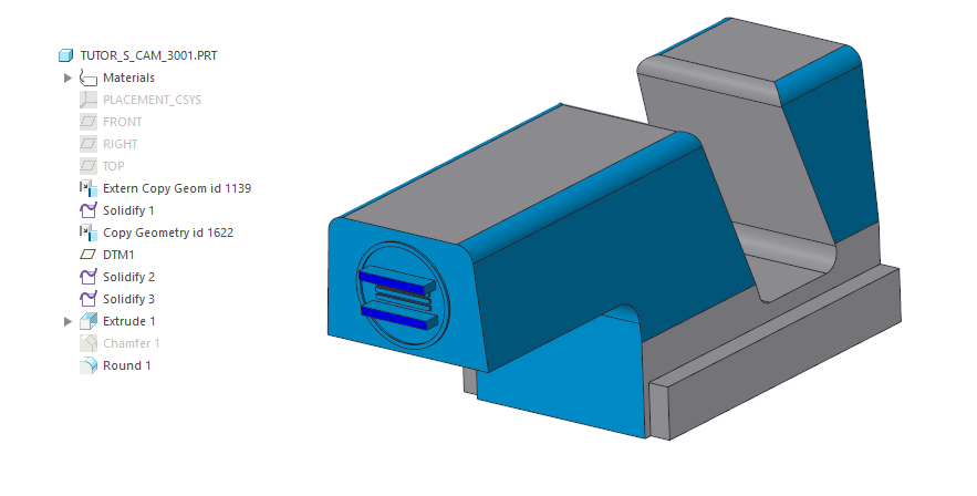
- Open the TUTOR_S_CAM_3001.PRT.
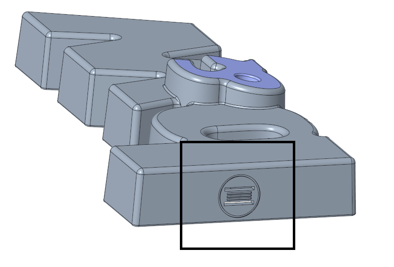
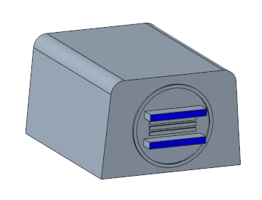
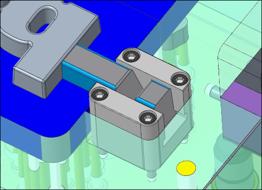
- Finish the slider design as seen in the image below using Solidify and Extrude features.
Remove Obsolete Quilt Cuts from Cavity Insert Parts
The cut quilt surface of the original slider assembly was interfering with the cavity insert parts.
These quilt cuts need to be removed.
- Open MOLD_VOL_IS_1.PRT.
- Delete the QUILT_CUT group MOLD_VOL_SLIDER_1.PRT which was created by the slider assembly.
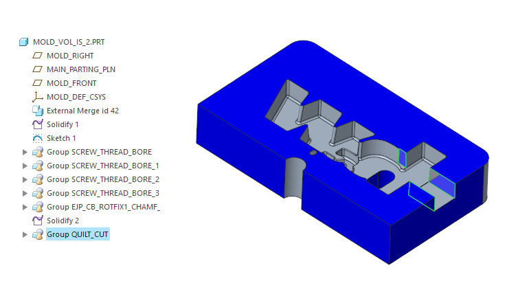
- Repeat this steps for:
- MOLD_VOL_IS_2.PRT
- MOLD_VOL_ES_1.PRT
- MOLD_VOL_ES_2.PRT
- MOLD_VOL_CORE_1.PRT
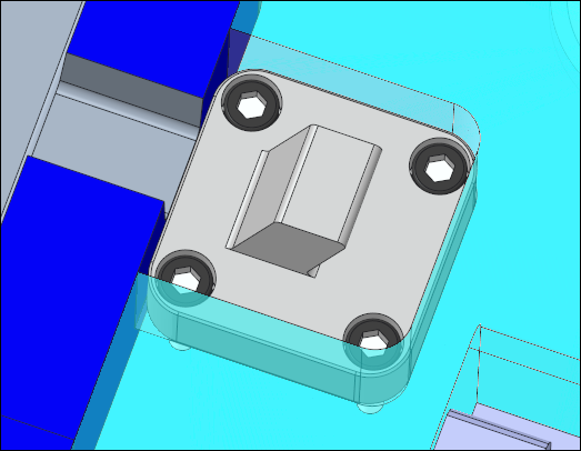
Assemble Screws to Fixture the Slider Components
- Assemble E1200/6x50 screws to fixture the slider guide component to the moving half.
- Make sure the Option Pattern for all models is active
- Assemble E1200/6x16 screws to fixture the slider bar component to the fixed half.
- Make sure the Option Pattern for all models is active