To Edit Mold Base Patterns
Download 15_To Edit Mold Base Patterns to start from with this chapter.
- Click
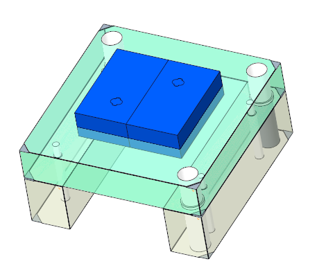
 Top to switch to the top view of the mold base.
 - Select the Main Guide 1
 pattern.
- Either by double-click inside the top view
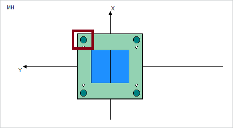
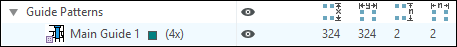
- Or by double-click on the listed pattern inside the summary tree.
The Pattern dialog box appears.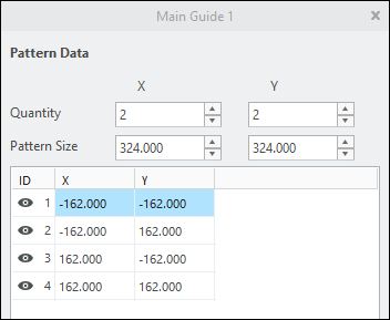 If a plate supplier provides default dimensions for a certain pattern in its catalog, this values will be used as default in the entries Quantity and Pattern Size.
 - Either by double-click inside the top view
- Click the visibility icon symbol
 in the first column. The icon switches to
  which indicates that this pattern instance should be removed from the axis-pattern.
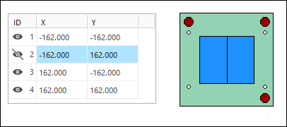
- Close the dialog with OK. The modification will be applied to the mold base assembly model.
- Reopen the Main Guide 1 pattern dialog box
- Modify the Y entry for Pattern Size to 200.
- Recalculate the pattern members with the
 button. The preview in Mold Base Definition shows the new position automatically without regeneration of the 3D model.
 - Close the dialog with OK. The modification will be applied to the mold base assembly model.
- Reopen the Main Guide 1 pattern dialog box
- Reset the Y entry for Pattern Size to 324.
- Click again.
- Close the dialog with OK.The pattern is set back to the default values.
Using 1+3 patterns
A common technique to avoid assembling mistakes of the mold base stack is to assemble leader pins and bushings with different
inner diameter at one pattern instance.
- Reopen the Main Guide 1 pattern dialog box
- Click
 .Only the pattern leader of Main Guide 1 remains visible. In addition the pattern Main Guide 2 is added with same Quantity and Pattern Size. In Main Guide 2 only the first position is suppressed. The different patterns are represented in Mold Base Definition by different colors.
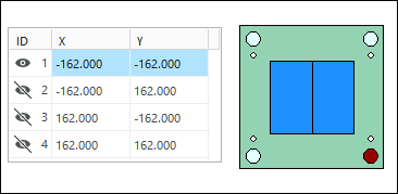
- Close the Main Guide 1 dialog box with OK.The suppressed pattern MAIN_GUIDE2 is resumed in the skeleton model, position and amount of axis match to the definition you have made.