To Use Mold Analysis to Check the Wall Thickness
Download 47 To Use Mold Analysis to Check the Wall Thickness to start from with this chapter.
Run an Mold Analysis for the Cavity Insert Part
The Mold Analysis for Creo Mold Design is a perfect tool to check the cooling circuit design.
- Open the MOLD_VOL_ES_1.PRT.
- Click The Creo Mold Design ribbon is activated.
- Click .the Mold Analysis dialog box opens.
- For Minimum Clearance set 4 mm.
- Click Compute to run the wall thickness check.The result is displayed in the graphics window.Several issues are found:
- Interferences with screw hole.
- Interferences with screw hole.
- Interferences with screw hole.
- Cooling channel is too close to ejector pin bores.
Design measures are require to fix these problems. - Close the Mold Analysis dialog box with Close.
- Click to return to the Creo part mode.
Fix Issues discovered by Interference Check
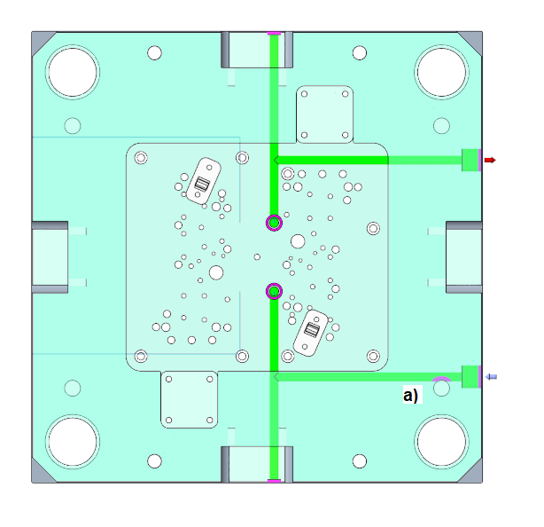
- Modify the Sketch 1 in the model tree to rearrange the screws.
- Move the points to a position simillar to the image displayed below.
- Open the MOLD_VOL_ES.PRT model.
- Modify the Sketch 1 in the model tree to adapt the curves.Make sure the angular curve has an sufficient distance to the reference model geometry.
- Open the TUTORORIAL.ASM.
- Regenerate the mold base assembly.
- Return to the MOLD_VOL_ES_1.PRT.
- Run the Mold Analysis again.The previously discovered issues are resolved.
- Return to the main assembly TUTORIAL.ASM.
Run an Mold Analysis for the Cavity Plate in the Moving Half
- Open the TUTOR_CAV_PLATE_MH_001.PRT.
- Run a Mold Analysis.The result is displayed in the graphics window.
 One issue is found:
- The cooling channel interferes with the clamping screw.
- Modify the Sketch 1 in the model tree to rearrange the curves.
- Run the Mold Analysis again.The previously discovered issue is resolved.
- Return to the main assembly TUTORIAL.ASM.