To Calculate the Clamping Force
Calculate Clamping Force for Insert Parts only
EMX offers the possibility to calculate the necessary clamping force depending on the projection of the reference model.
- Select
- Insert the Injection Pressure value. If a machine was defined in Mold Base Definition, the Machine Clamping Force can be found in the top-right corner.
- Start a Calculation with
 .
EMX displays the projection in the Drawing Area.
.
EMX displays the projection in the Drawing Area.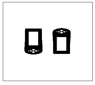 As a result you will get the Projected Area and the Req. Clamping Force.
Assemble a Runner
It is possible to add runners to the projection. Before you can assemble the runner make sure you have the correct sprue bushing
assembled.
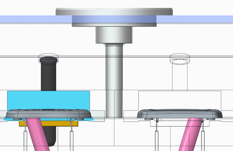
The Sprue Bushing should reach down to the separation plane of the mold base.
Runner can be found in the Component Library. You can define as many different runners as you want. Look for this in chapter To Add a Part to the Library
- Select
 .
. - Select the directory runner from the directory tree.
- Select part runner2 with Double-Click.
- Set the OFF_PLUS_Y value to 25.
- Set the OFF_MINUS_Y value to 25.
- As assembly reference for runners (1) CSYS the coordinate system ORIGIN_MOLDBASE is predefined.
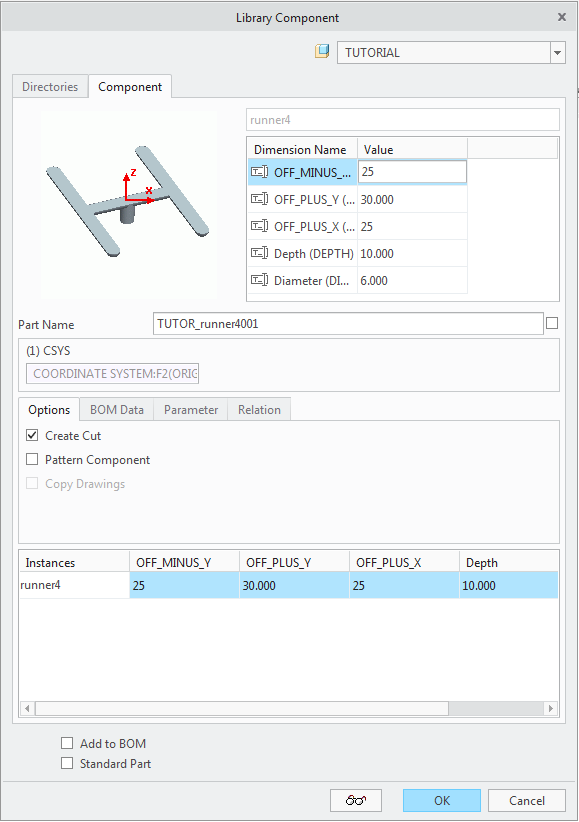
- Leave the Library dialog box with OK. The runner is assembled to the TUTORIAL.ASM and cut outs are added to the moving half insert parts MH_PALM_1.PRT and MH_PALM_2.PRT.
Calculate Clamping Force for Insert Parts and Runners
- Click .
- Click
 to add a runner to the projection.
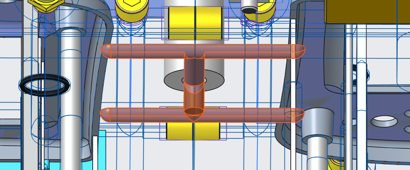
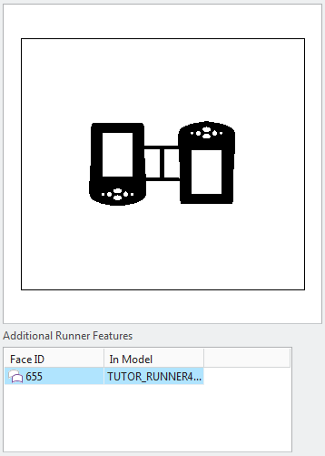
- Select the quilt of the previously created runner in the graphic window.
The result can be seen in the Calculate Clamping Force dialog box. The runner is displayed in the Drawing Area as well.
Calculate the MOULDING plastic part
While opening this Clamping Force dialog box, a second action can be run by EMX that is related to the Projected Area calculation.
- Click again.
Now you are prompted to select the MOULDING model that was designed previously. EMX will find all ejector pin cutouts and remove them from the MOULDING.