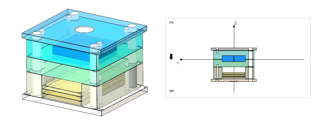
To Finish the Plate Stack
Download 16_To Finish the Plate Stack to start from with this chapter.
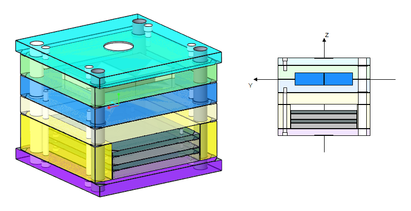
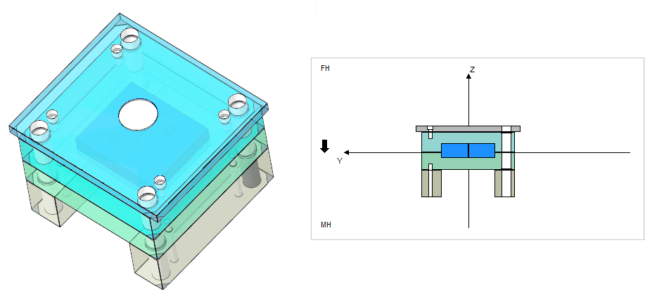
Add a cavity plate to the fixed half.
- Open the Mold Base Definition dialog box.
- Click with right-mouse button within the fixed half of the side view and click
 Add plate above
  Cavity PlateThe Plate dialog box opens.
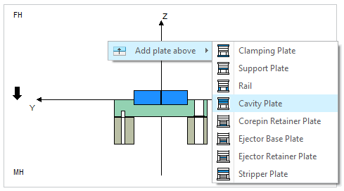
- Select subassembly TUTOR_FH.
- Select type F50.
- Select Thickness 86.
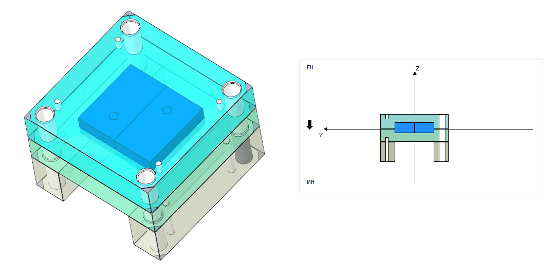
- Close the Plate dialog box with OK. The cavity plate is assembled.
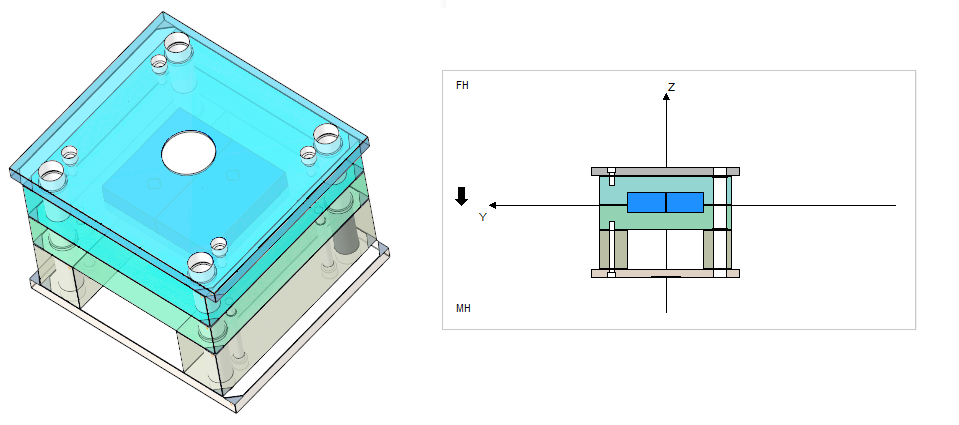
Add a clamping plate to the fixed half.
Add a clamping plate to the moving half.
Add a core pin retainer plate.
Add an ejector base plate.
- Click with right-mouse button on the cavity plate within the fixed half of the side view and click Add plate above
 Clamping Plate
 - Select TUTOR_FH as Subassembly.
- Click OK to leave the Plate dialog box.
- Click with right-mouse button on the rail within the moving half of the side view and click
 Add plate below Clamping Plate
 - Select TUTOR_MH as Subassembly.
- Click OK to leave the Plate dialog box.
- Click with right-mouse button on the clamping plate within the moving half of the side view and click Add plate above
 Corepin Retainer Plate
 - Select TUTOR_MH as Subassembly.
- Set Reference Distance to 4 mm to leave some space for the stop system.
- Close the dialog with OK.
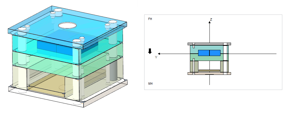
- Click with right-mouse button on the core pin retainer plate within the moving half of the side view and click Add plate above Ejector Base Plate
- Select TUTOR_MH as Subassembly.
- Set Reference Distance to 0 mm.
- Close the dialog with OK.
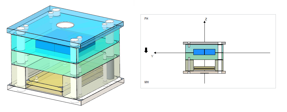
Add an ejector retainer plate.
- Click with right-mouse button on the ejector base plate within the moving half of the side view and click Add plate above
 Ejector Retainer Plate
 - Select the Ejector Base Plate as placement reference in the Side View.
- Select TUTOR_MH as SubassemblyClose the dialog with OK.