To Create a Lifter
Download 43 To Create a Lifter to start from with this chapter.
Create a Lifter
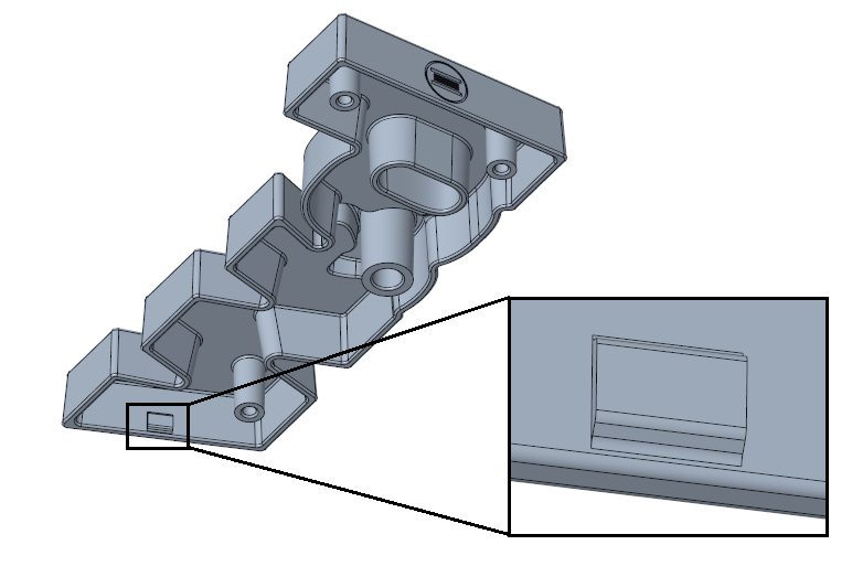
In this tutorial a lifter is designed to create the snap connection on the bottom side of the plastic part ARTICLE_REF.PRT.
- Open the mold base TUTORIAL.ASM.
- Display the Moving Half of the mold base.
- Click
 .The Lifter dialog opens.
 - Select TUTOR_MH from the Subassembly pull-down menu.
- Select Supplier meusburger.
- Select the Type E3246_E3240.
- Define the references.
- Click (1) Csys and select the CSYS_LIFTER coordinate system in the ARTICLE_REF.PRT.
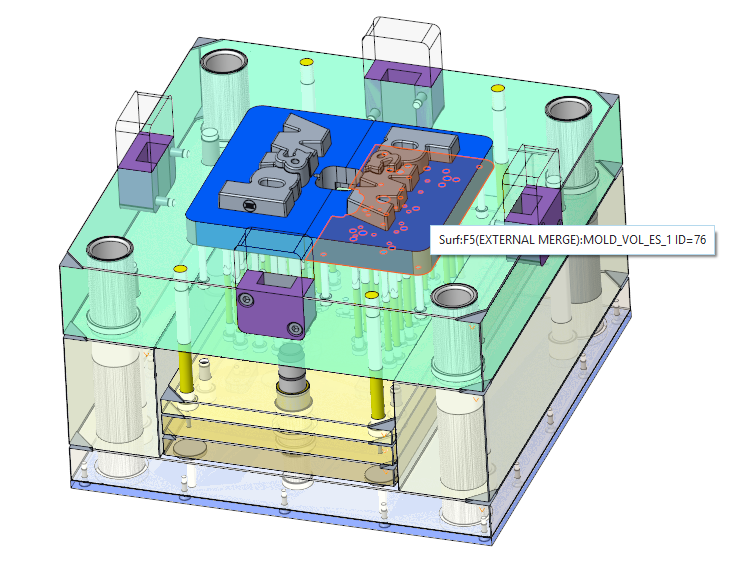
- For reference (6) Surface select the bottom surface of the cavity insert part MOLD_VOL_ES_1.PRT.
- Reference (4) Plane Guide and (5) Plane Retainer are set by default.
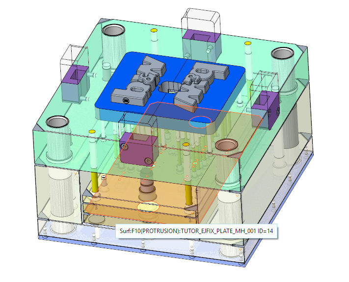
- Click on (5) Plane Retainer to redefine this reference.Select the top surface of the ejector plate TUTOR_EJFIX_PLATE_MH.PRT.
- Make sure that the option Trim to quilt/refmodel is enabled.
- Enable the Option Pattern for all models.
- Assemble the lifter with
 Preview.
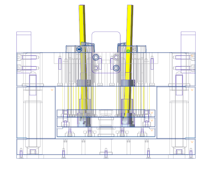 The position of the lifter is not correct and needs to be adapted.
 - Set the ALPHA value to 6 ° to adjust the position.
- Set the STROKE_Z value to 15 mm to adjust the position.
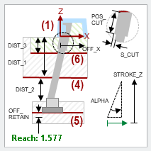
- Click Preview again.The Reach value is set to 1.577 mm.The snap connection has a height of 1 mm.The resulting reach is larger then the required reach.
- Set the OFF_X value to -1.4 mm to adjust the position.This ensures the lifter bar position is correctly interfering with the reference mode
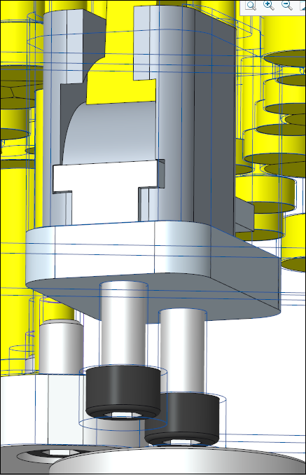
- Set the OFF_Z_RETAIN value to 6 mm to adjust the position.This ensures the lifter retainer is not interfering with any ejector pins.
- Set the CUT_S value to 2 mm.This will create a step within the lifter bar. This step avoids damage to the ejector plates due to the high pressures during the injection molding procedure.
- Assemble the lifter again with Preview.The resulting trimmed lifter bar is previewed.
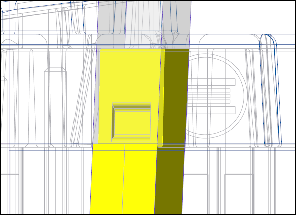 The position of the lifter is good, no other components are interfering.
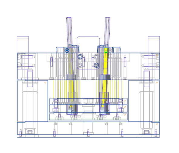
- Finally assemble the lifter with OK.The trimmed lifter is assembled to the mold base and all cuts are created.
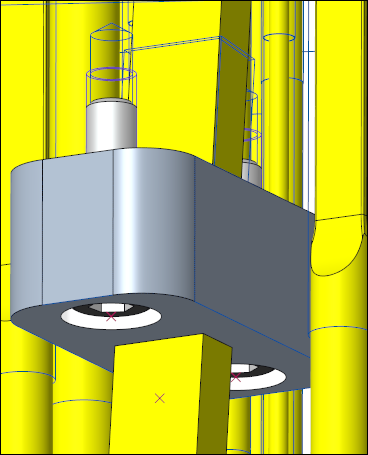
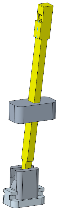 The lifter creates now the contour of the snap connector and releases it during the mold base opening process.
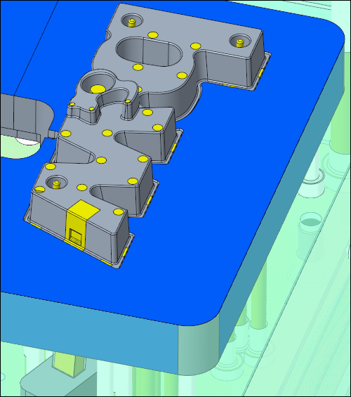
Create Screws for the Lifter
- Assemble E1200/5x20 screws to fixture the retainer to the TUTOR_EJFIX_PLATE_MH_001.PRT.Make sure to assemble them with Pattern for all models.
- Assemble E1200/5x16 screws to fixture the guide to the TUTOR_CAV_PLATE_MH_001.PRT.Make sure to assemble them with Pattern for all models.