To Assemble Cooling Components on Curves
Download 46 To Assemble Cooling Components on Curves to start from with this chapter.
Sketch the Cooling System Curves
Depending on the requirements sketched curves can be used to define the cooling bore position.
In this tutorial a cooling is added to the cavity plates and the cavity insert parts.
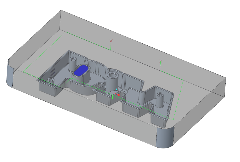
- Open the MOLD_VOL_ES.PRT.
- Set the bottom side of the model to a transparent color.A sketch curve can be discovered within the cavity insert part.This sketch curves can also be used in the duplicated cavity insert parts MOLD_VOL_ES_1.PRT and MOLD_VOL_ES2.PRT.
- Close the MOLD_VOL_ES.PRT model and return to the main assembly.
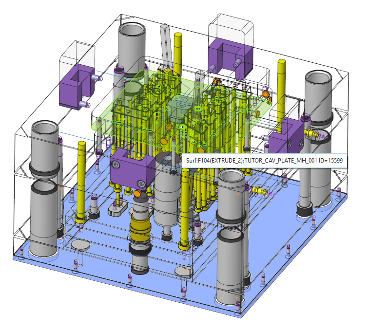
- Open the TUTOR_CAV_PLATE_MH_001.PRT.
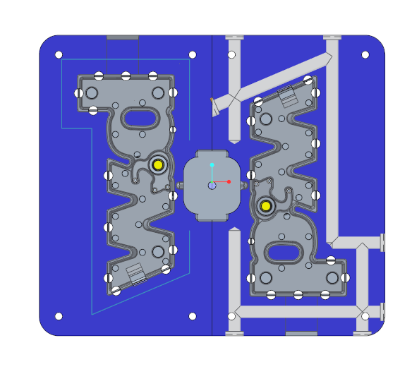
- Create a sketch within the cavity plate similar to the image below.As a placement reference a datum plane is used with an offset of 20 mm.
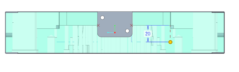 Make sure the sketch refers to the sketch created in the MOLD_VOL_ES.PRT.
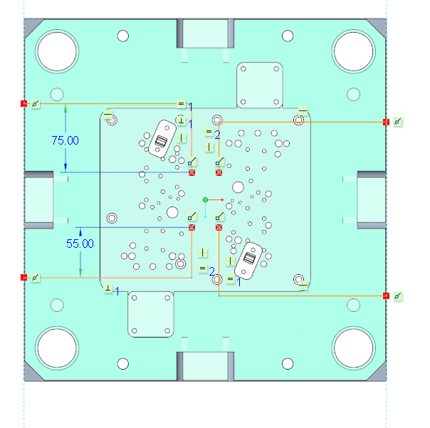
- Close the TUTOR_CAV_PLATE_MH_001.PRT model and return to the main assembly.
Add Cooling Components on Sketched Curves
- Open the subassembly TUTOR_SHARED.ASM.
- Open the MOLD_VOL_ES_1.PRT and MOLD_VOL_ES_2.PRT
- Set the bottom side of the models to a transparent color.This improves the visibility of the curves.
- Select EMX Components Cooling Component
 Cooling Component.The Cooling Component dialog box opens.
 - Select meusburger from the Supplier pull-down menu.
- Select E2072 from the Type pull-down menu.
- Select 12 mm for the DM3 nominal value.
- Define the references.
.
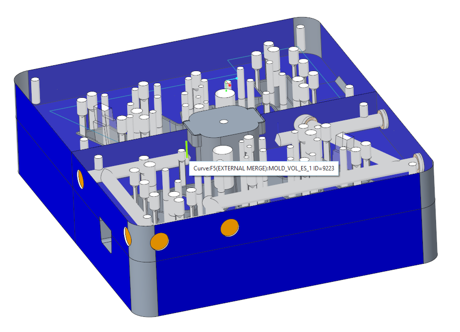
- Click (1) Curve|Axis|Point and select one of the curves created in the MOLD_VOL_ES.PRT.
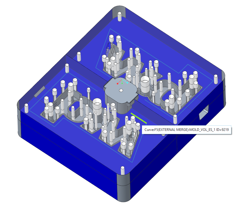
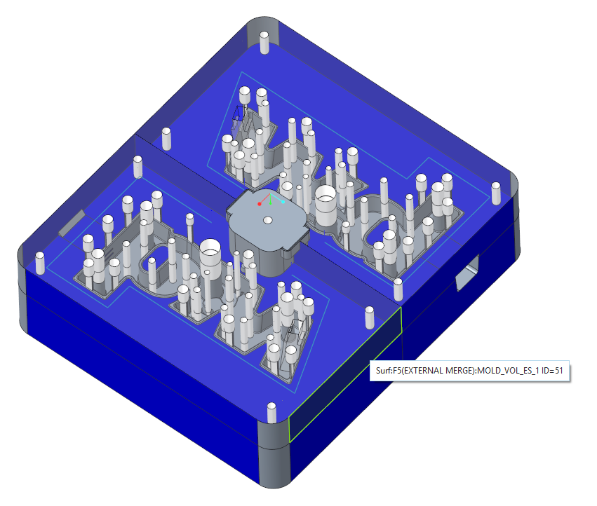
- Click (2) Surface and select the side surface of the MOLD_VOL_ES_1.PRT.
- Click (1) Curve|Axis|Point and select one of the curves created in the MOLD_VOL_ES.PRT.
- Click OK to assemble the cooling component.The cooling component and the related cuts are created.
- To place the same cooling component again select
- a curve
- a surface
- a curve
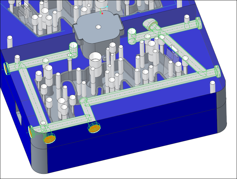
- Finish the cooling circuit.
- Leave the loop with middle mouse button and click Cancel to close the dialog box.
Modify Counter Bore Depth of Cooling Component
Several cooling components need some modification to finish the placement.
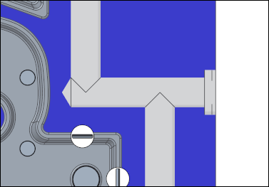
- Select the cooling component which is placed on the angular curve either in the model tree or in the graphics window.
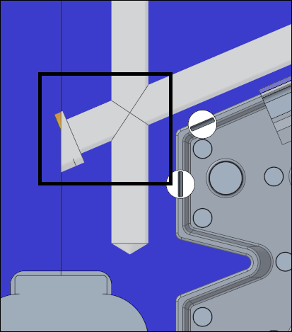
- Click
 Modify from the mini toolbar or the right-Mouse menu.The Cooling Component dialog box opens.
 - In the UDF Dimension table set the T3 value to 6 mm.
- Click OK to adapt the modifications to the cooling component.The counter bore has now a depth of 6 mm.
Modify Additional Bore Depth of Cooling Component
Some cooling components need an additional drill depth to ensure that the cross-section of the cooling circuit always has
the required diameter.
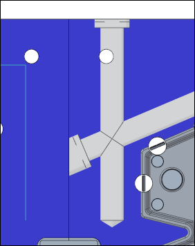
- Select the cooling component displayed in the image below either in the model tree or in the graphics window.
- Click Modify from the mini toolbar or the right-Mouse menu.The Cooling Component dialog box opens.
- In the UDF Dimension table set the T5 value to 4 mm.
- Click OK to adapt the modifications to the cooling component.
Add Vertical Holes on Sketched Curves
To finish the circuit two vertical holes need to be assembled.
The vertical holes are the connections to the cavity plate on the moving half.
- Select EMX Components Cooling Component Cooling Component.The Cooling Component dialog box opens.
- Select meusburger from the Supplier pull-down menu.
- Select Hole from the Type pull-down menu.
- Select 8 mm for the NOM diameter value.
- In the UDF Dimension table set the T5 value to 4 mm to ensure the additional bore depth.
- Define the references.
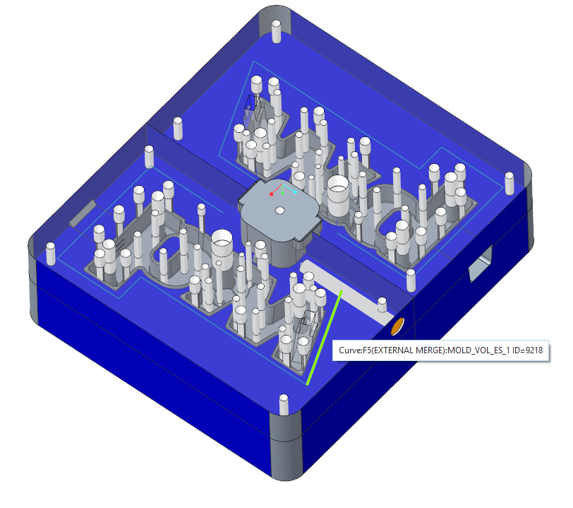
- Click (1) Curve|Axis|Point and select one of the vertical curves created in the MOLD_VOL_ES.PRT.
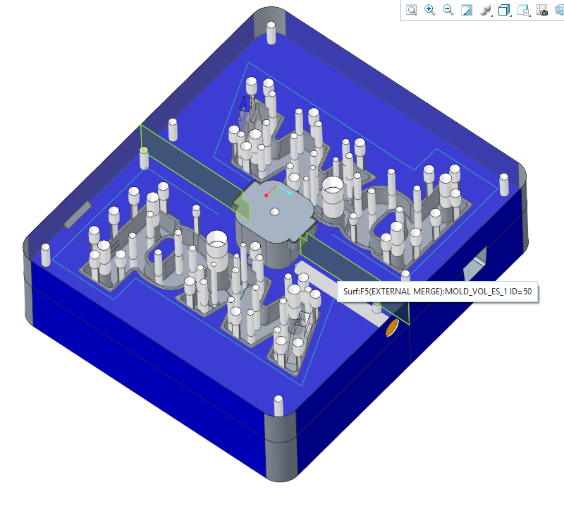
- Click (2) Surface and select the bottom surface of the MOLD_VOL_ES_1.PRT.
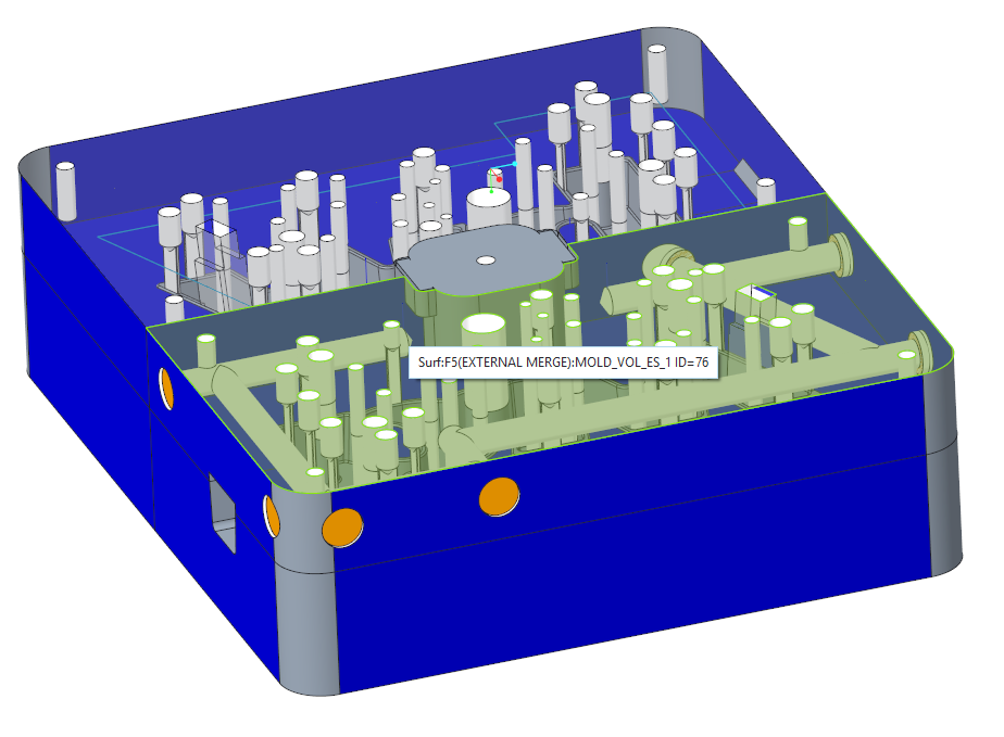
- Click (1) Curve|Axis|Point and select one of the vertical curves created in the MOLD_VOL_ES.PRT.
- Assemble the second vertical hole in the quick selection loop.
- Leave the loop with middle mouse button and click Cancel to close the dialog box.The cooling circuit in the cavity insert parts is finished.
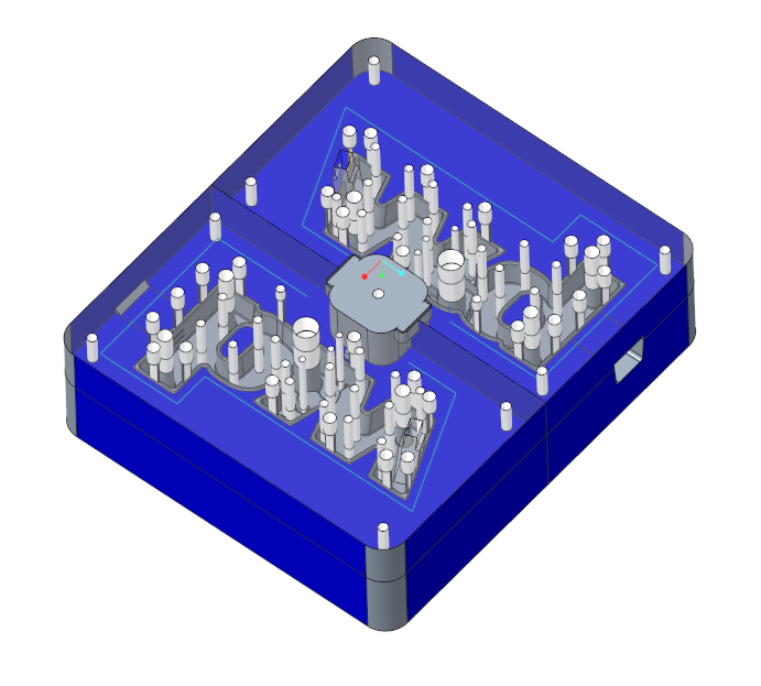
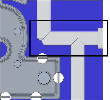
Assemble Related Cooling Channels to Cavity Plate on the Moving half
In a first step, two cooling nipples are defined for the inflow and outflow.
- Open the subassembly TUTORIAL.ASM.
- Click EMX Assembly View
 Wireframe Style.
 - Click EMX Assembly View Show
 Moving Half.
 - Select EMX Components Cooling Component Cooling Component.The Cooling Component dialog box opens.
- Select TUTOR_MH from the Subassembly pull-down menu.
- Select meusburger from the Supplier pull-down menu.
- Select E2000 from the Type pull-down menu.
- Select 9 mm for the DM2 diameter value.
- Define the references.
- Click (1) Curve|Axis|Point and select one of the curves created in the TUTOR_CAV_PLATE_MH_001.PRT.
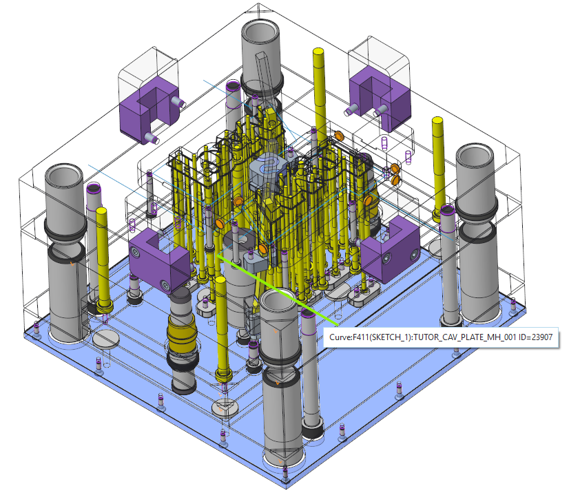
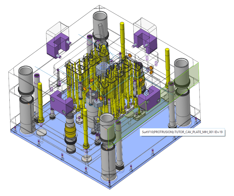
- Click (2) Surface and select the front surface of the TUTOR_CAV_PLATE_MH_001.PRT.
- Click (1) Curve|Axis|Point and select one of the curves created in the TUTOR_CAV_PLATE_MH_001.PRT.
- Click OK to assemble the component.
- Repeat the steps for the second cooling nipple.
Assemble two additional seal plugs
- Select EMX Components Cooling Component Cooling Component.The Cooling Component dialog box opens.
- Select TUTOR_MH from the Subassembly pull-down menu.
- Select meusburger from the Supplier pull-down menu.
- Select E2072 from the Type pull-down menu.
- Select 12 mm for the DM3 diameter value.
- Define the references.
- Click (1) Curve|Axis|Point and select one of the curves created in the TUTOR_CAV_PLATE_MH_001.PRT.
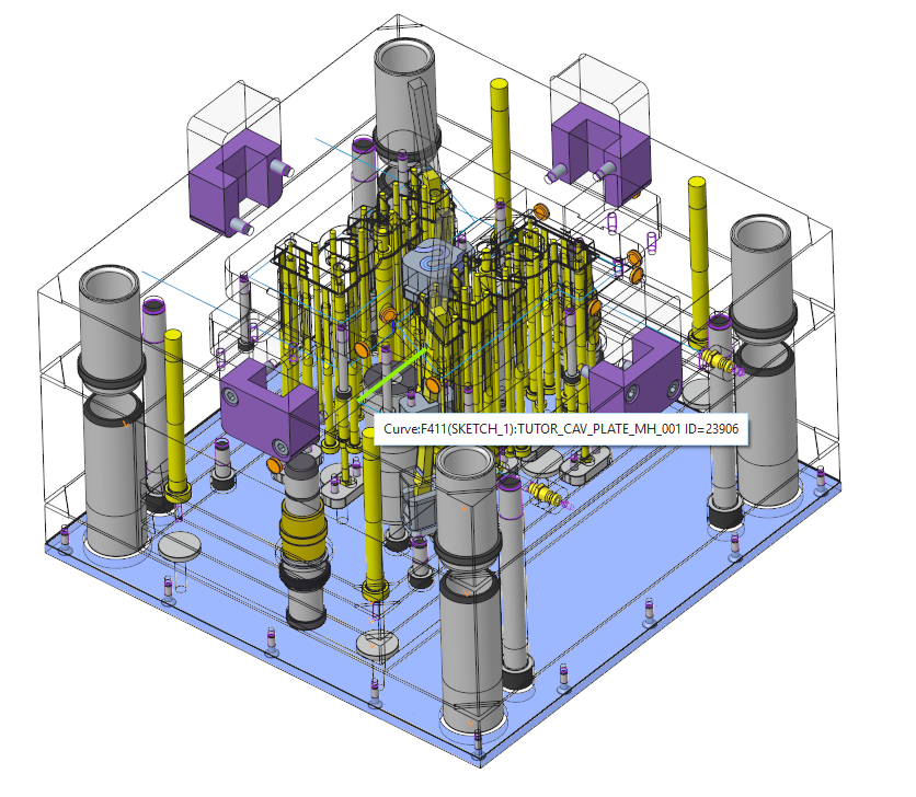
- Click (2) Surface and select the left surface of the TUTOR_CAV_PLATE_MH_001.PRT
- Click (1) Curve|Axis|Point and select one of the curves created in the TUTOR_CAV_PLATE_MH_001.PRT.
- Click OK to assemble the component.
- Repeat the steps for the second seal plug
Assemble two additional o-rings
Two additional o-rings have to be assembled to the vertical curves as connection to the cavity insert part.
- Select EMX Components Cooling Component Cooling Component.The Cooling Component dialog box opens.
- Select TUTOR_MH from the Subassembly pull-down menu.
- Select meusburger from the Supplier pull-down menu.
- Select E2130 from the Type pull-down menu.
- Select 11 mm for the DM1 diameter value.
- In the UDF Dimension table set the T5 value to 4 mm to ensure the additional bore depth.
- Define the references.
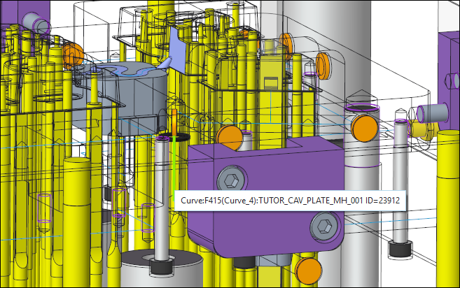
- Click (1) Curve|Axis|Point and select one of the curves created in the TUTOR_CAV_PLATE_MH_001.PRT.
- Click (2) Surface and select the left surface of the TUTOR_CAV_PLATE_MH_001.PRT.
- Click (1) Curve|Axis|Point and select one of the curves created in the TUTOR_CAV_PLATE_MH_001.PRT.
- Click OK to assemble the component.
- Repeat the steps for the second seal plug.All cooling components for the first cooling circuit are assembled.