To Apply a Set of Measurement Points for 3D Measurement
Create Reference CSYS
EMX supports the usage of 3D measurement for Quality Assurance. To define the required position for the probe ball of the
measurement machine you need to know its center position normal to the face where the "real" point to be measured is located.
EMX can calculate this position for you.
- Open the mold base TUTORIAL.ASM.
- Open the model MH_PALM_1.PRT.
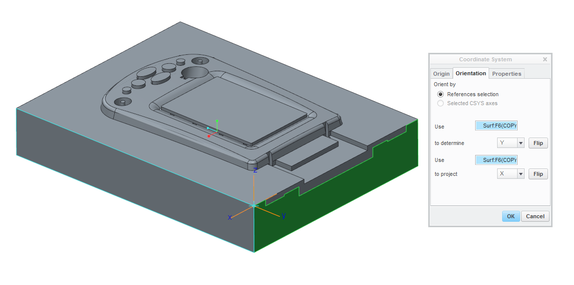
- Create a coordinate system as shown below. This coordinate system will be used as reference for the set of measurement points. The direction of the z-axis is important if you like to add a full set of points in one step.
- Make sure Show 3D Notes is enabled.
Add Single Measurement Points
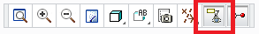
- Select .The Measuring Points dialog opens.
- Select
 to identify the reference coordinate system.
- Select the previously created CS0.
- Click
 and pick the points to be measured on the models top face.With each pick a note is displayed with the real x,y,z position regarding CS0 and the required probe ball position. The position is also listed in the Point list of the Measurement Points dialog box.
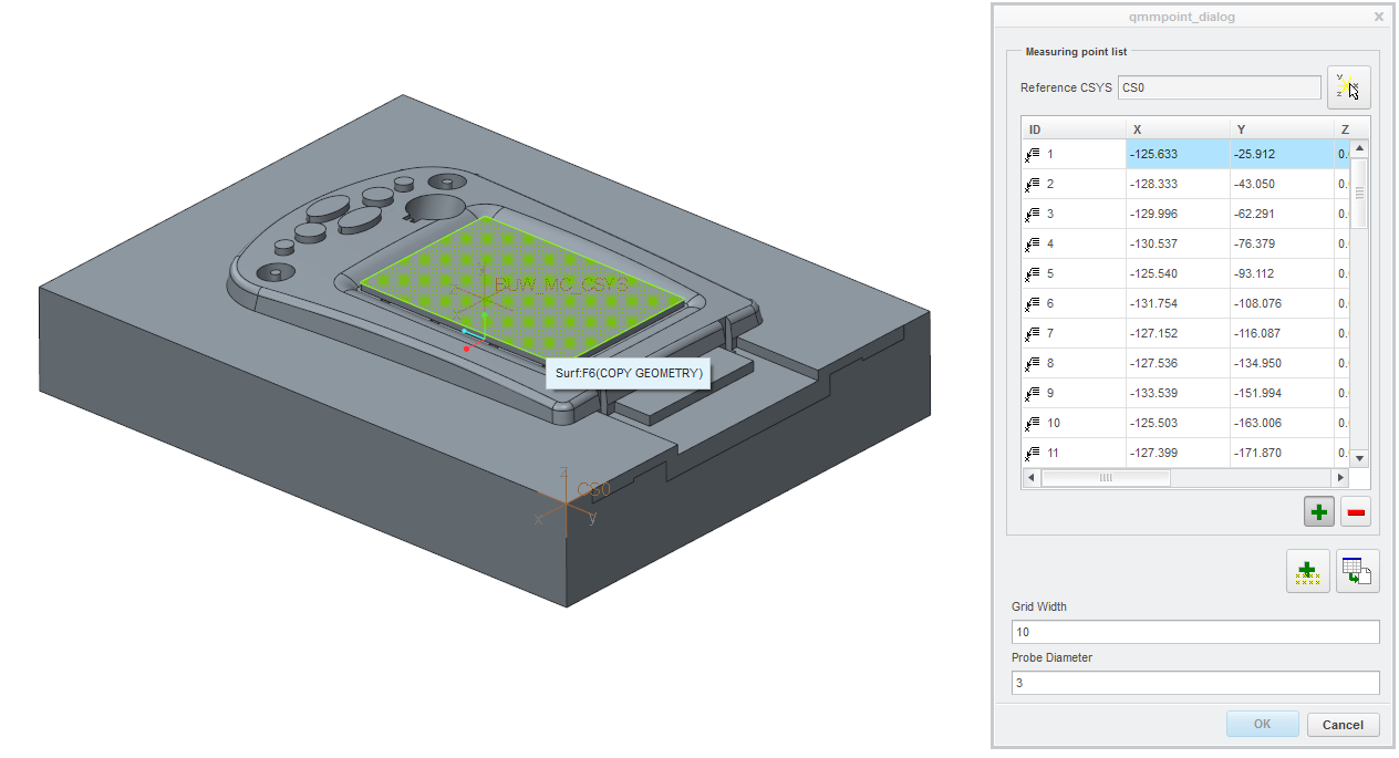
- Cancel the input loop with MMB.If you select a line from the points list its related note gets highlighted in the graphics window.
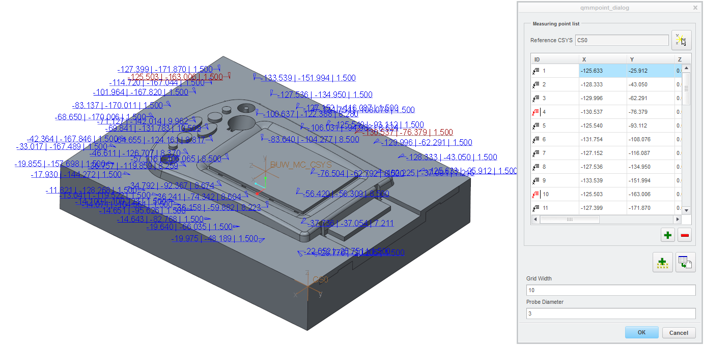
- Close the Measurement Points dialog box with OK.A point feature is added to the current model MH_PALM_1. Each entry of the Measurement points list is represented by an extra point.
Export List of Points
- Select .EMX will read the stored positions of all points again and displays them in the Measurement points list.
- Select any line to highlight the according point in 3D.
- Click
 .The content of the list is written to file specified in EMX Option QMM_FILENAME. By default the file will be stored in the working directory.
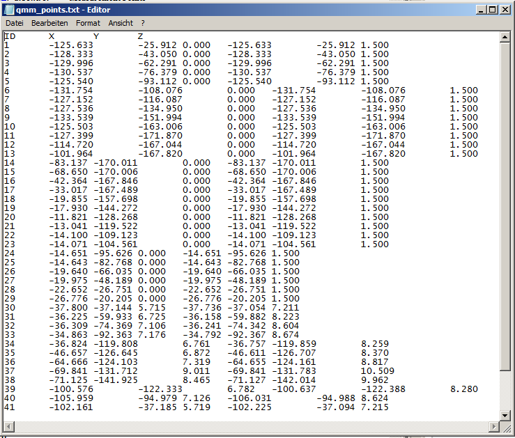
Create a Grid of Measurement Points
- Delete the previously created point feature and the annotations.
- Select again.
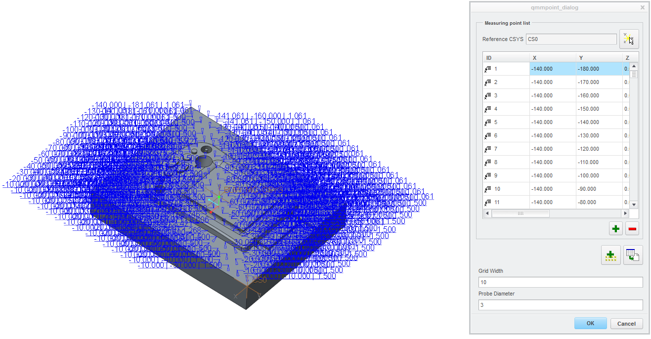
- Set the Grid Width of the point pattern to 10.
- Start the creation process of the points pattern with
 . A set of Measurement Points with a constant distance of 10 mm is added to the MH_PALM_1.PRT.