To Assemble Ejector Guide Bushings and Pins
Download 21_To Assemble Ejector Guide Bushings and Pins to start from with this chapter.
Set up the Ejector Guide Pattern
- Open the Mold Base Definition dialog box.
- Click
 Top to switch to the top view.
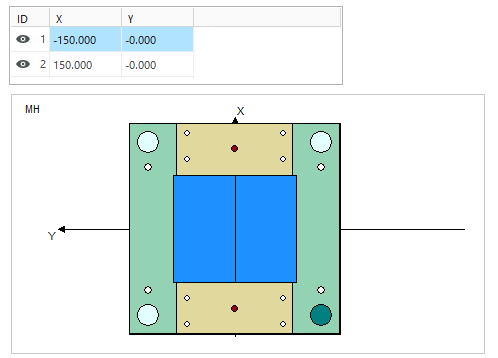
- Double–click the Ejector Guide MH either in the top view or in the summary tree.The Ejector Guide MH dialog box opens.
- Enter Quantity 2 in both X direction.
- Enter Quantity 1 in both Y direction.
- Enter a value of 280 in X direction.
- Click Recalculate
 to update the instances.
- Close the Ejector Guide MH dialog box with OK.
Add Ejector Guide Bushings
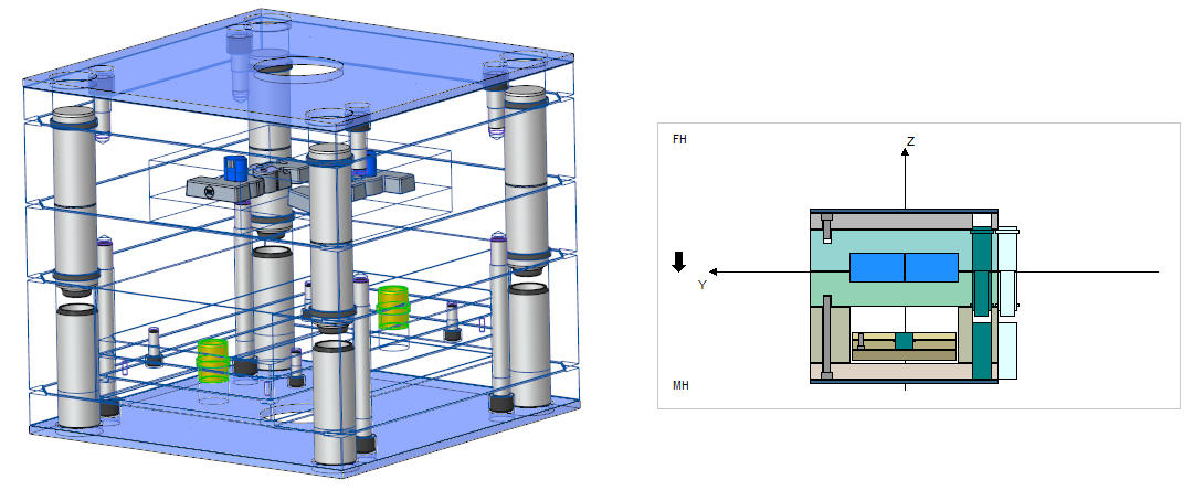
- Click
 Front to switch to the side view.
 - Click with right-mouse button on the Ejector Base Plate either in the side view or in the summary tree. Click
 Add guide
  Ejector Guide Bush.The Guides dialog box opens.The TUTOR_MH subassembly is already preselected .
 - Set the DM2 value to 24.
- Set the LG1 value to 22.
- Set the LG2 value to 17.
- Make sure that the Option Toggle Direction is enabled. This option specifies whether the bush shoulder is located in the ejector base plate or the ejector retainer plate.
- Close the Guides dialog box with OK and answer the message box with OK.The ejector guide bushes are assembled to the mold base assembly.
- Close the Mold Base Definition with Close.
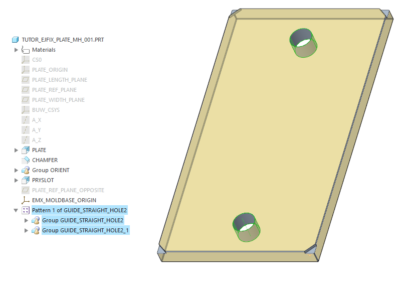
Remove Cutouts from Ejector Core Pin
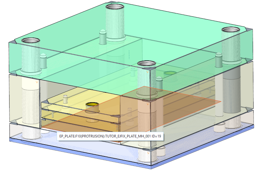
- Open the part TUTOR_EJFIX_PLATE_MH_001.PRT.
- Delete the group GUIDE_STRAIGHT_HOLE
Add Ejector Guide Bush with Circlip to the Core pin Plate
- Open the TUTOR_MH subassembly.
- Select EMX Components Components Guide Component.The Guides dialog box opens.
- Select TUTOR_MH as target subassembly from the subassembly pull down list.
- Select E1110_ from the types pull down list.
- Set the DM1 value to 30.
- Set the DM2 value to 24.
- Set the LG value to 22.
- As the first assembly reference (1) Axis|Point select the datum axis EJP_GUIDE from the pattern inside the TUTOR_SKELETON.PRT Model.
- As the second assembly reference (2) Surface select the bottom side of the core pin plate.
- Enable the option One Plate.A different UDF Images appears in the cut out section. Circlip and shoulder cutouts are added to the same plate.
- Switch to the Options tab and check the option Pattern for all instances to create a guide component for each axis inside the pattern.
- Close the Guide dialog box with OK.The guide bushed and the according cutouts for the core pin plate are assembled to the moving half assembly.
- Close the TUTOR_MH.ASM and switch back to the main assembly.
Add Ejector guide Pins
- Open the Mold Base Definition dialog box.
- Click with right-mouse button on the Clamping Plate MH either in the side view or in the summary tree. Click Add guide
 Ejector Leader Pin.The Guides dialog box shows up.The TUTOR_MH subassembly is already preselected .
 - Set the DM1 value to 24.
- Set the LG value to 160.
- Close the Guide dialog box with OK and answer message box with OK.
- Close the Mold Base Definition with Close.The leader pins are assembly to the mold base.
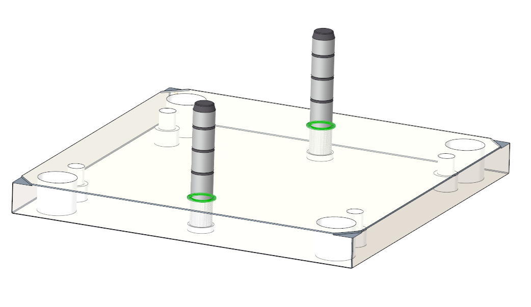
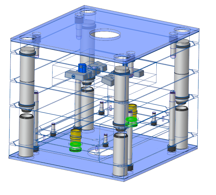
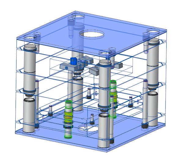 To fix the leader pins, circlips can be used. The image bellow shows a design example.