To Add Predefined Screws to Components
- Erase all models from the Creo session.
- Open part E1920.PRT from directory library/tutorial.
- Create a Datum Axis
 at each of the existing bores.
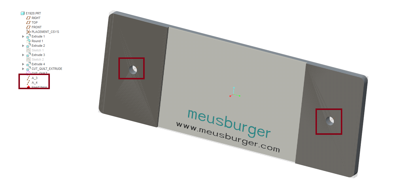
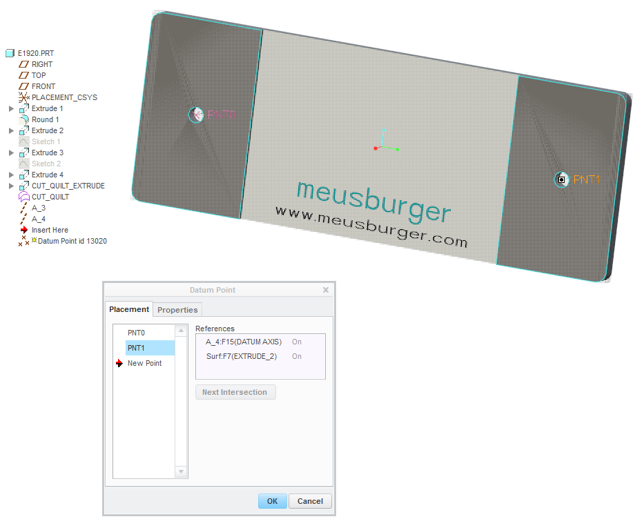
- Create a Datum Points
 on each of the recently created axes and the upper surface of the plat as seen in the picture below.
- Click
 .
.

- Within the Screw dialog box select the desired screw supplier meusburger and screw type E1200 | Socket head cap screw
- Define the references.
- Click (1) Point|Axis and select the recently created datum points.
- (2) Surface - Select the top face of the E1920.PRT.
- (3) Thread surface - Select the bottom face of the E1920.PRT.
- Double click the Diameter Value and select 4.
- Double click the Length Value and select 10.
- Make sure that Counterbore is disabled.When working in Part Mode, the Predefined Component flag is set by default.
- Leave the Screw dialog box with OK and find the predefined component UDFs in the model tree.
- Save the modified library part with File > Save.
Assemble the Modified Library Component
- Open the mold base TUTORIAL.ASM
- Assemble the E1920.PRT as described in the chapter Add a Part to Library.
- Select
 .
. - Select the model TUTOR_E1920008 in the graphics window.
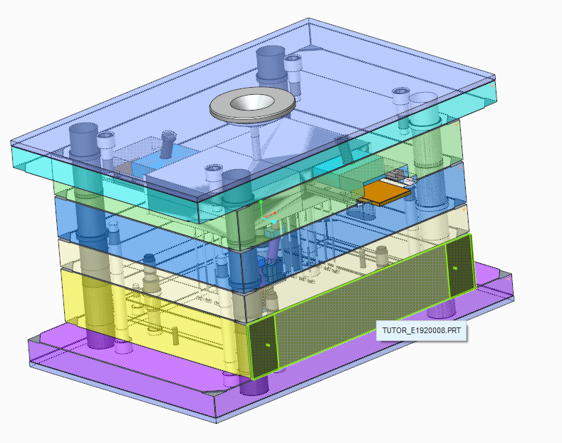 As the result the predefined screws are assembled to the mold base.
Background Information
Set the EMX Option AUTO_ASSEMBLE_SCREWPINS to YES to assemble predefined components directly after assembling the owner component automatically.
This way of predefining components can be used for any EMX component, even sliders or lifters. But in most cases it is dowel
pins and screws that are predefined.