To Assemble Screws on Insert Parts
Download 29 To Assemble Screws on Insert Parts to start from with this chapter.
Create Points on Insert Parts
- Open MOLD_VOL_IS_1.PRT.
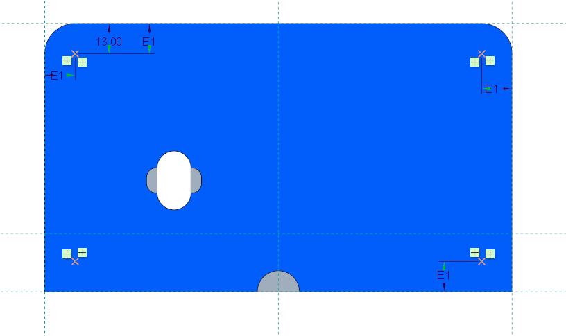
- Create sketched datum points on the top surface of the model as seen in the image below.
- Close MOLD_VOL_IS_1.PRT and return to TUTORIAL.ASM.
- Repeat these steps for the parts MOLD_VOL_IS_2.PRT, MOLD_VOL_ES_1.PRT and MOLD_VOL_ES_2.PRT.
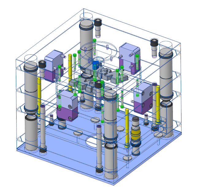
- Regenerate the Assembly TUTORIAL.ASM.
Assemble the Screws for the Fixed Half insert Parts
- Click
 .
.
- Select TUTOR_FH as target subassembly form the subassembly pull-down list.
- Define the references.
- Click (1) Point/Axis and select the recently defined points from MOLD_VOL_IS_1.PRT.
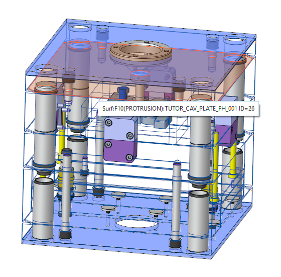
- As (2) Surface select the top surface of the cavity plate TUTOR_CAV_PLATE_FH_0001.PRT.
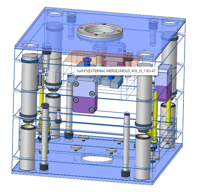
- As (3) Thread Surface select the top surface of the MOLD_VOL_IS_1.PRT insert.
- Select DM1 — Diameter 8 mm.
- Select LG1 — Length 50 mm.
- Close the Screw dialog box with OK.
- Repeat these steps for the MOLD_VOL_IS_2.PRT model.
Assemble the Screws for the Moving Half insert Parts
- Click .
- Select TUTOR_MH as target subassembly form the subassembly pull-down list.
- Define the references.
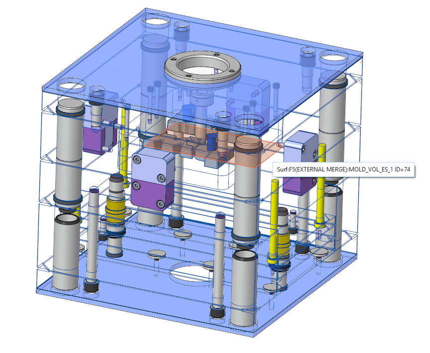
- Click (1) Point/Axis and select the recently defined points from MOLD_VOL_ES_1.PRT.
- As (2) Surface select the bottom surface of the cavity plate TUTOR_CAV_PLATE_MH_001.PRT.
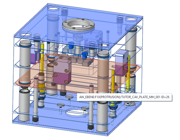
- As (3) Thread Surface select the bottom surface of the MOLD_VOL_ES_1.PRT insert.
- Select DM1 — Diameter 8 mm.
- Select LG1 — Length 45 mm.
- Close the Screw dialog box with OK.
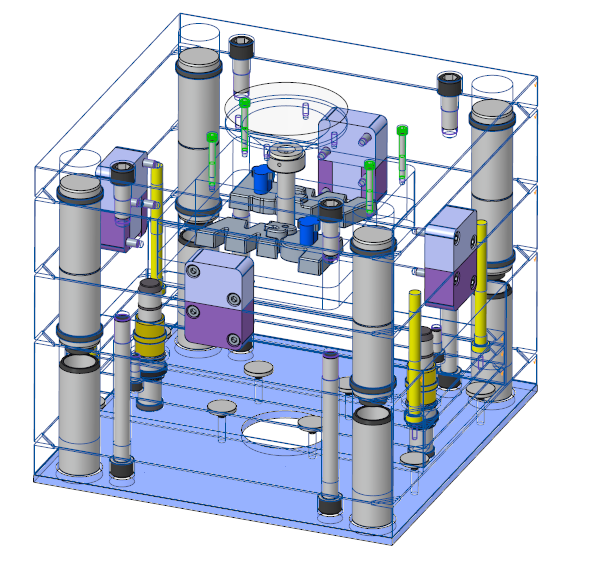
- Repeat these steps for the MOLD_VOL_ES_2.PRT model.In total 16 screws should be assembled to the mold base.