To Assemble Main Guide Components
Download 17_To Assemble Main Guide Components to start from with this chapter.
Add Centered Guide Bush to first Guide Pattern Scheme
Before adding a guide component, specify the guide-pattern scheme to be used as assembly reference.
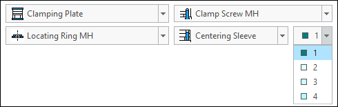
- Open the Mold Base Definition dialog box.
- Select
 1 from the Pattern Scheme pull down in the right bottom corner of the dialog.
- Click with the right-mouse button on the moving half cavity plate in the summary tree and click
 Add guide
  Centered Guide Bush .
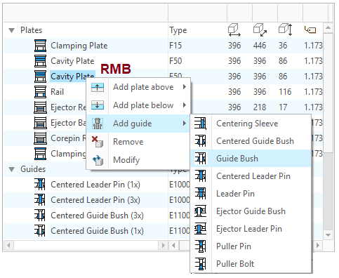 The Guides dialog box appears.
 - Make sure the TUTOR_MH subassembly is selected before you continue.
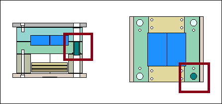
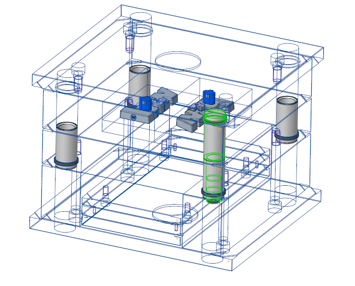
- Close the dialog box with OK. The guide bush is displayed in the same color like the pattern in the top view. So you can see which components are related to which pattern position.
Set the Assembly Status of Components
There is no solid guide component to the assembly TUTOR_FHassembled yet.
- Close the Mold Base Definition dialog box
- Click EMX Assembly Mold Base
 Component Status.
 - Check all component types with
 .
. 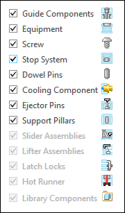
- Close the dialog box with OK.From now on all solid component model will be assembled directly.
- Click EMX Assembly View
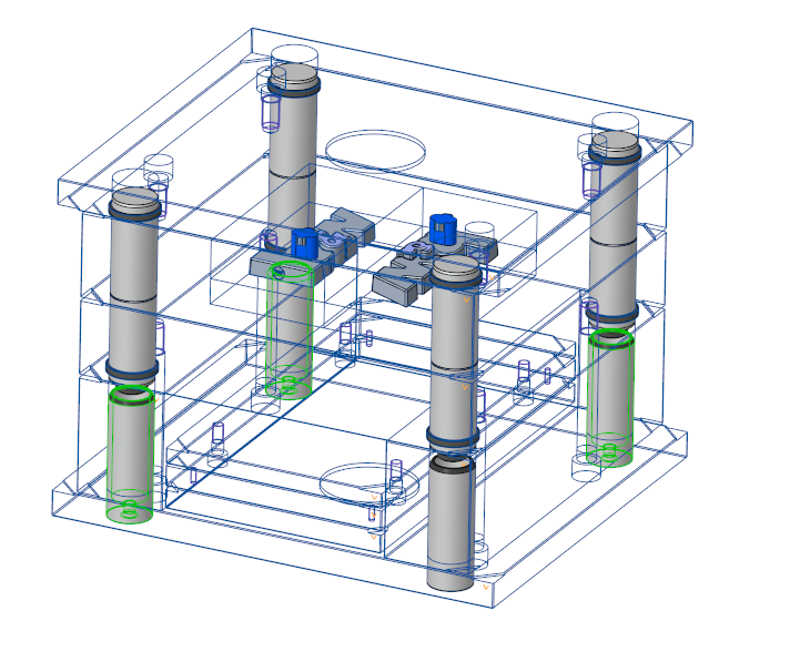
 Wireframe Style.The centered guide bush component is now assembled.
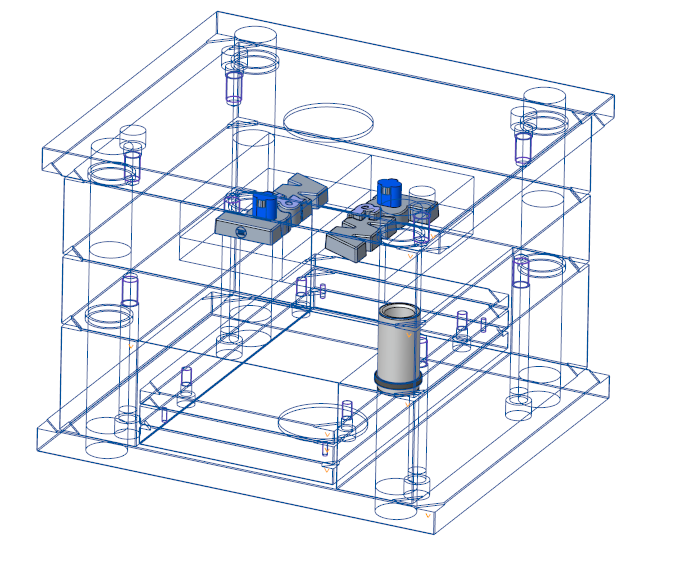
Add Additional Centered Guide Bushes to second Guide Pattern Scheme
Add additional bushes with a different inner diameter on the second axis pattern.
- Open the Mold Base Definition dialog box.
- Select
 2 from the Pattern Scheme pull down in the right bottom corner of the dialog.
 - Click again with the right-mouse button on the moving half cavity plate in the summary tree and click Add guide Centered Guide Bush.The Guide dialog box opens.The second inner diameter is set to 32 mm for DM2 automatically.
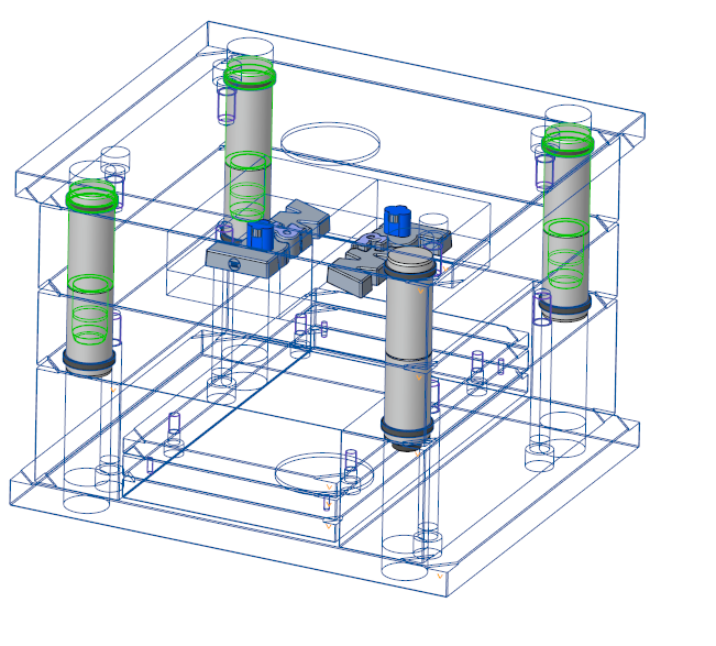
- Click OK to assemble the guide components.The bush on the second pattern is displayed beside the bush on first pattern in the side view. The color is equals to the color of the second pattern.
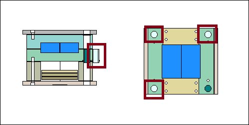 Three additional guide bushes are assembled to in the mold.
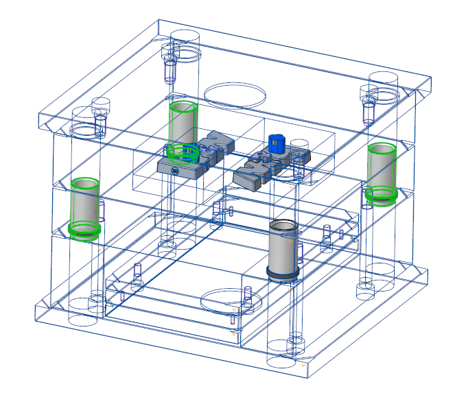
Add Leader Pins
- Select 1 from the Pattern Scheme pull down in the right bottom corner of the dialog.
- Click with the right-mouse button on the fixed half cavity plate in the summary tree and click Add guide
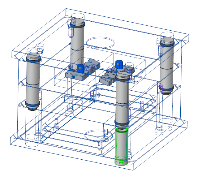
 Centered Leader Pin.The Guide dialog box opens.TUTOR_FH is already preselected as the target subassembly.The inner diameter DM2 must be set to 30 mm to fit to the according bush. This is already preselected.
 - Select 95 mm for LG2
- Click OK to leave the Guides dialog box.
- Select 2 from the Pattern Scheme pull down in the right bottom corner of the dialog.
- Select the Cavity Plate MH with LMB in the Side View as placement reference.Make sure TUTOR_MH is the target subassembly. DM2 must be 32 mm now.
- Click with the right-mouse button on the fixed half cavity plate in the summary tree and click Add guide Centered Leader Pin.The Guide dialog box opens.TUTOR_FH is already preselected as the target subassembly.The inner diameter DM2 must be set to 32 mm to fit to the according bush. This is already preselected.
- Select 95 mm for LG2.
- Click OK to leave the Guide dialog box.
Add Centering Sleeves
- Select 1 from the Pattern Scheme pull down in the right bottom corner of the dialog.
- Click with the right-mouse button on the moving half clamping plate in the summary tree and click Add guide
 Centering sleeve.The Guide dialog box opens.TUTOR_MH is already preselected as the target subassembly.
 - Set the LG value to 120.
- Click OK to leave the Guide dialog box.
- Select 2 from the Pattern Scheme pull down in the right bottom corner of the dialog.
- Click with the right-mouse button on the moving half clamping plate in the summary tree and click Add guide Centering sleeve.The Guide dialog box opens.TUTOR_MH is already preselected as the target subassembly.
- Set the LG value to 120.
- Click OK to leave the Guide dialog box.