To Assemble Core Pins in Insert Parts using the Option “As Core Pin in One Plate”
Download 37 To Assemble Core Pins in Insert Parts using the Option As Core Pin in One Plate to start from with this chapter.
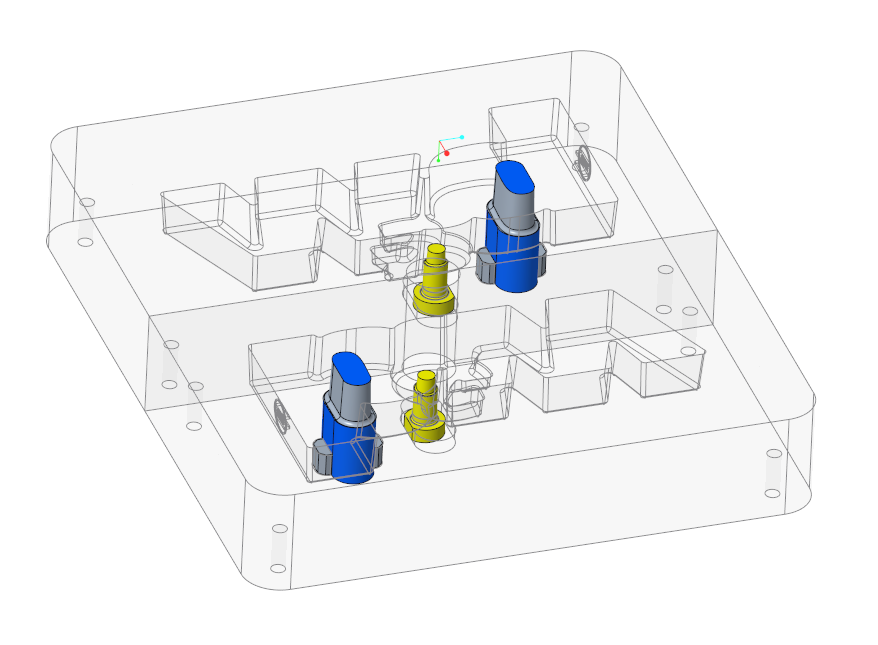
Assemble Core Pin to Insert Parts On the Fixed Half
- Click EMX Assembly View
 Wireframe Style.
 - Click EMX Components
 Ejector Pin.The Ejector Pin dialog box opens.
 - Select TUTOR_SHARED as target subassembly from the subassembly pull-down list.
- Select knarr from the Supplier pull-down list.
- Select 37111 from the Types pull-down list.
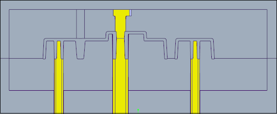
- Set the DM1 value to 8.2 mm
- Define the references
- Click (1) Point to select the point from the multi point feature PNTS_COREPIN_2 in the ARTICLE_REF.PRT model.The LG1 value is automatically set to 160 mm.
- Click (2) Surface to select a different placement plane. Select the top surface of the insert part MOLD_VOL_IS.
 The LG1 value is updated to 100 mm.
- Click (1) Point to select the point from the multi point feature PNTS_COREPIN_2 in the ARTICLE_REF.PRT model.
- Make sure that the Trim to quilt/ refmodel check box is enabled.
- Make sure that the As core pin in one plate check box is enabled.
- Select
 Rotfix1 from the Fix Rotation pull-down list.
 - Make sure Pattern for all models is enabled.
- Close the dialog box with OK to assemble the trimmed core pins.