To Assemble Ejector Pins
Download 32 To Assemble Ejector Pins to start from with this chapter.
Assemble the Ejector Pin Target Subassembly
- Click EMX Assembly Structure
 Add SubassembliesThe Subassembly dialog box opens.
 - Select TUTOR_MH from the Subassembly pull-down list.
- Enter TUTOR_MH_EPINS into the Name input panel.
- Select Ejector Pins from the Function pull-down list.
- Click OK to leave the Subassembly dialog box.A new EMX Subassembly will be added to the mold base assembly.With the assigned Ejector Pins function all upcoming ejector pins will by default be assembled to this subassembly.
Define the Ejector Pin Properties
- Click EMX Assembly View Show
 Moving Half.
 - Select
 .The Ejector Pin dialog box opens.TUTOR_MH_EPINS is preselected as Subassembly.
 - Select knarr from the Supplier pull-down list.
- Select 37111 from the Types pull-down list.
- Set the DM1 value to 4 mm.
- Define the references
- For (1) Point select a point from the multi point feature PNTS_ROUND_EPIN_4MM in the ARTICLE_REF.PRT model.After the Point has been selected the offset between the point and the default reference surface will measured.This offset (157.541 mm) is shown in the Reference Distance line of the Dimensions.The next valid instance is chosen automatically in case an instance of this ejector pin exists, where the LG1 exceeds the measured distance.
- The (2) Surface reference will be selected automatically and is used to align the head of the ejector pin. By default the bottom face of
the first ejector retainer plate in the mold base is used.
- The (3) Orientation surface is preselected. The MOLDBASE_Y_Z of the skeleton model is used by default for all ejector pins.
- For (1) Point select a point from the multi point feature PNTS_ROUND_EPIN_4MM in the ARTICLE_REF.PRT model.
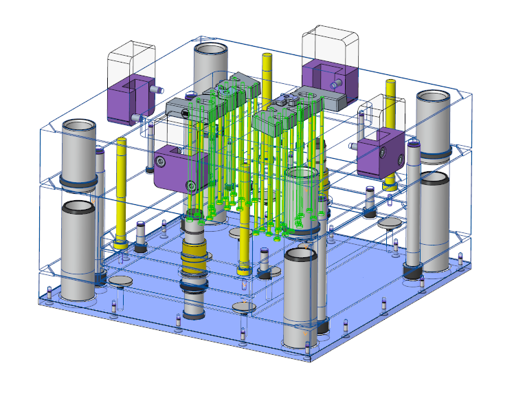
- Click Preview to visualize the ejector pins.On each point of the multiple point features an ejector pin is previewed.
- Enable the option Individual ejector models on each point. This option is necessary to be able to Trim the ejector pin heads after finishing the ejector pin placement.
- Make sure Auto Length is activated. With this option the length of the ejector is set to the Reference Distance value displayed in the dialog box.
- Switch to the Options tab and click Pattern for all models to add the ejector pins (and their cutouts) to both ARTICLE_REF.PRT models.
- Click Preview again to visualize the ejector pins.On each point of the multiple point features and on both reference models an ejector pin is previewed.
- Close the Ejector Pin dialog box with OK.The ejector pins and their according cutouts are assembled to the mold base.
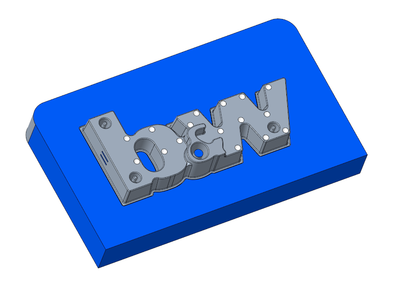
- Open the MOLD_VOL_ES_1.PRT model.All cut-outs are created on part level.The groups EJP_CB_ANGLE can be treated and handled like any other feature..
- Close MOLD_VOL_ES_1.PRT and return to the main assembly.