To Predefine Ejector Pins in Part Mode with Layout Curves
Download 39 To Predefine Ejector Pins in Part Mode with Layout Curves to start from with this chapter.
Identify the Ejector Pin owner model
- Open the TUTORIAL.ASMBefore adding ejector pins in part mode it is necessary to copy the placement reference datum plane for ejector pins in the model. Otherwise the required length of the ejector pins cannot be determined.
- Select EMX Components Ejector Pin Identify ejector pin owner models
 .
.
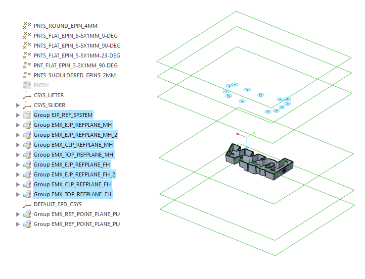
- Select the model ARTICLE_REF.PRTEMX adds two orientation planes normal to the splitting plane and a copy of each clamping plane, ejector reference plane, both fixed half and moving half.
- Click OK.
- Open ARTICLE_REF.PRT .
Predefine Ejectors in Part Mode
- Select EMX Part Mode Components
 Ejector Pin .The Ejector Pin dialog box shows up.
 - Select the Supplier knarr.
- Select the Type 32141DLC.
- Select SIZE 3.8x1.
- Set the REF_ANGLE value to 90.
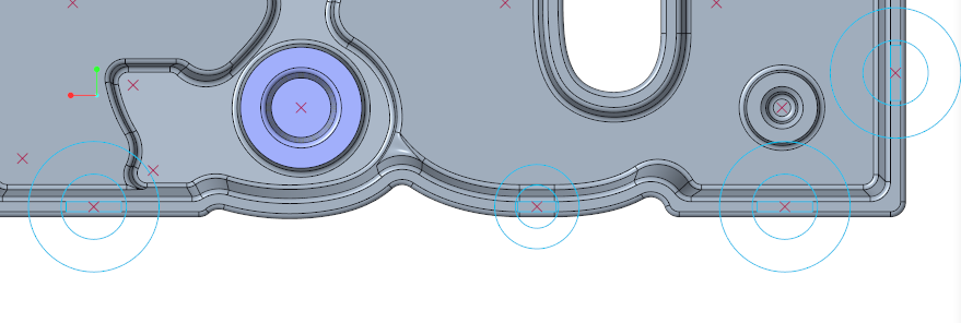
- Define the references.
- As first Reference (1) Point select a point from the multiple point feature PNT_FLAT_EPIN_3-2X1MM_90-DEG.
- As first Reference (1) Point select a point from the multiple point feature PNT_FLAT_EPIN_3-2X1MM_90-DEG.
- Make sure that the option Pattern for all models is enable.
- Make sure Trim to quilt/refmodel is enabled.
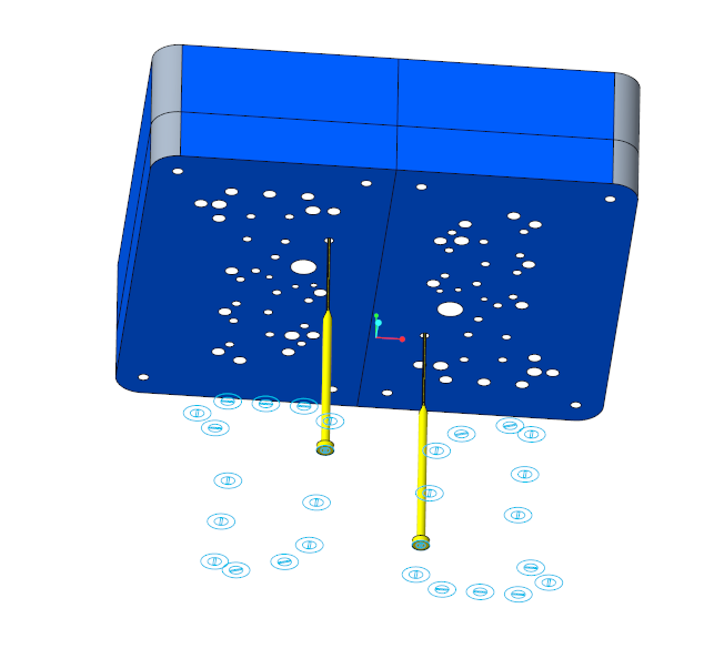
- Preview with

 An additional predefined layout curves of the ejector pin can be seen now.
 - Click OK to assembled the predefined components reference groups to the model.
- Close the ARTICLE_REF.PRT and go back to the TUTORIAL.ASM.
Assemble Ejector Pins with “Assemble predefined components”
- Open the TUTOR_SHARED.ASM.
- Click EMX Components Component Handling
 Assemble predefined components .A selection window shows up and asks for the assembly from which the predefined components should be assembled.
 - Select ARTICLE_REF.PRT. All ejector pins will be assembled.Cut-outs are only crated to the insert parts so far..
- Close TUTOR_SHARED.ASM and return to the main assembly TUTORIAL.ASM.
- Click from the Ejector Pin overflow menu.
All missing cut-outs are created to the mold base assembly