To Assemble Ejector Sleeves
Download 34 To Assemble Ejector Sleeves to start from with this chapter.
Assemble the Small Ejector Sleeves
- Click EMX Assembly View
 Wireframe Style.
 - Click EMX Assembly View Show
 Moving Half.
 - Click EMX Components
 Ejector Pin.The Ejector Pin dialog box opens.The TUTOR_MH_EPINS assembly is preselected.
 - Select knarr from the Supplier pull-down list.
- Select 38188 from the Types pull-down list.
- Click RMB on the Value column of Diameter.
- Pick Measure Diameter from the Measure Popup Menu.
- Select the edge as displayed below. The measured diameter will be displayed in an EMX message box with 4.221 mm.
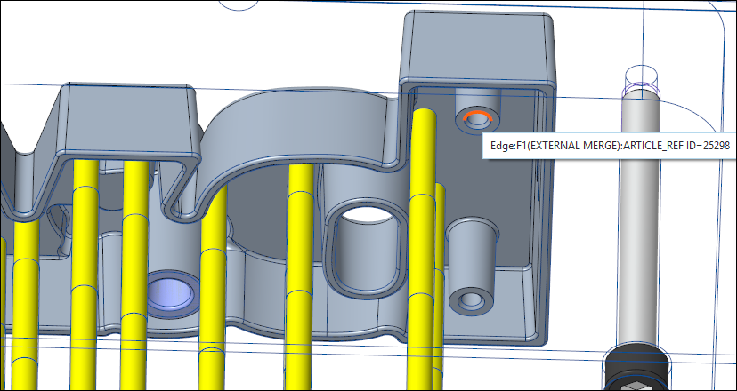
- Set the inner diameter DM1 value to 4.5 mm which is the next larger diameter comapre to the measured value.
- Set the outer diameter DM3 value to 7 mm.
- Define the references
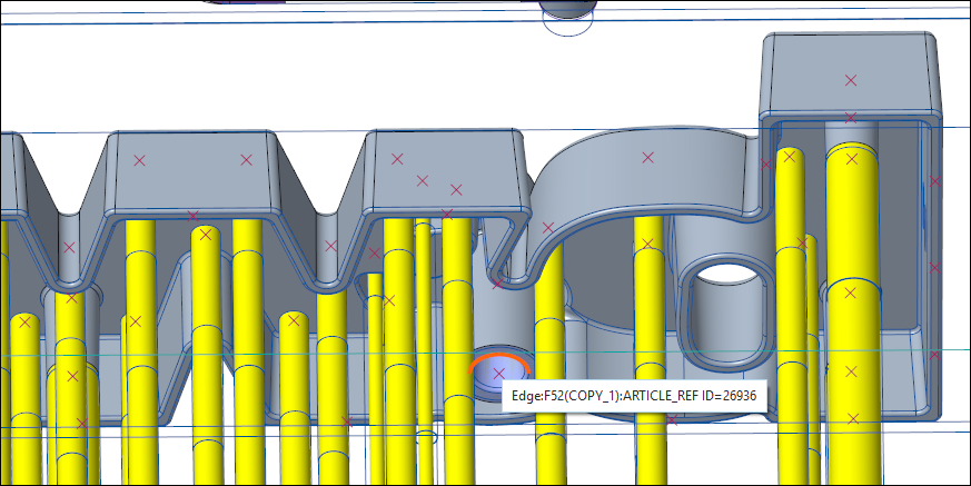
- For (1) Point select a point from the multi point feature PNTS_SLEEVE_1 in the ARTICLE_REF.PRT model.The LG1 value is automatically set to 150 mm.
- For (1) Point select a point from the multi point feature PNTS_SLEEVE_1 in the ARTICLE_REF.PRT model.
- Make sure Pattern for all models is enabled.
- Make sure Individual ejector models on each point is enabled.
- Make sure that the Auto Length check box is enabled.
- In the UDF Dimension set the LL value to 25 mm.
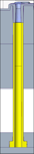
- Close the dialog Box with OK. The ejector sleeves are added to the moldbase.
Assemble the Large Ejector Sleeves
- Click EMX Components Ejector Pin.The Ejector Pin dialog box opens.The TUTOR_MH_EPINS assembly is preselected.
- Select knarr from the Supplier pull-down list.
- Select 38188 from the Types pull-down list.
- Click RMB on the Value column of Diameter.
- Pick Measure Diameter from the Measure Popup Menu.
- Select the edge as displayed below. The measured diameter will be displayed in a message box with 8.023 mm
- Set the inner diameter DM1 value to 8.2 mm which is the next larger diameter compare to the measured value.
- Define the references
- For (1) Point select a point from the multi point feature PNTS_SLEEVE_2 in the ARTICLE_REF.PRT model.The LG1 value is automatically set to 150 mm.
- For (1) Point select a point from the multi point feature PNTS_SLEEVE_2 in the ARTICLE_REF.PRT model.
- Make sure Pattern for all models is enabled.
- Make sure that the Auto Length check box is enabled.
- In the UDF Dimension set the LL value to 30 mm.
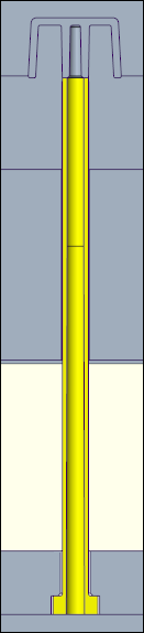
- Close the dialog Box with OK. The ejector sleeves are added to the mold base.