To Assemble Ejector Pins using the Ejector Pin Designer
Download 38 To Assemble Ejector Pins using the Ejector Pin Designer to start from with this chapter.
Start the Ejector Pin Designer
- Open the assembly TUTORIAL.ASM
- Click
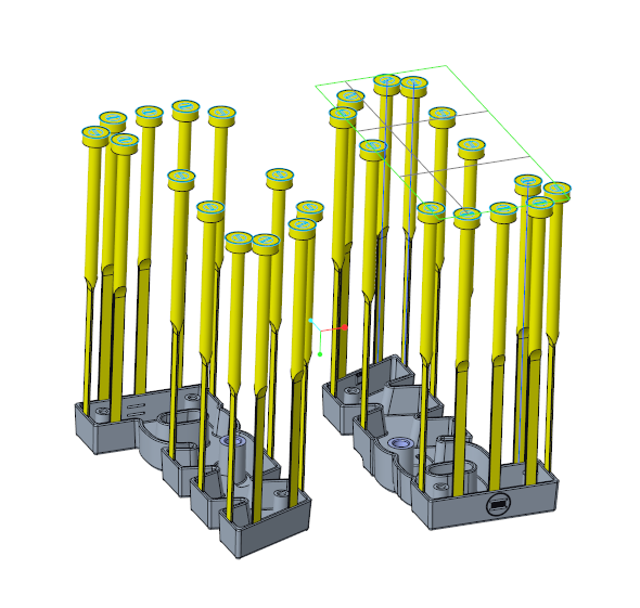
 . The Ejector Pin Designer opens.A simplified representation which only contains the reference models and all ejector pins defined with the Ejector Pin Designer is activated.So far no ejector pins are defined by the Ejector Pin Designer.The outline of the reference model is displayed as a green rectangle.
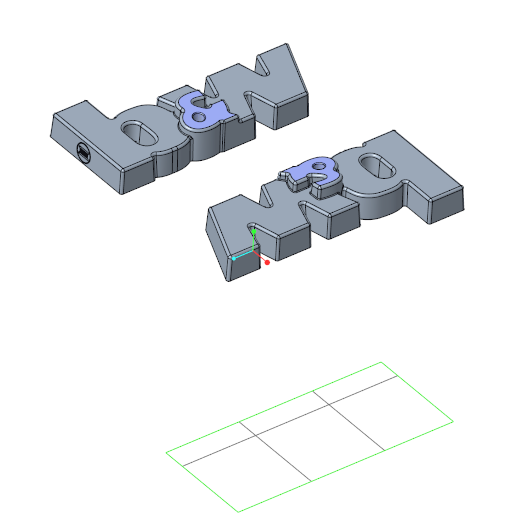
- Use the default setting:
- Define on the reference model ARTICLE_REF.PRT.
- Assemble to the moving half MH.
- Place the ejector to the first ejector package Ejector Plate #1.
Manage Type Preselection
- Click
 to preselect another ejector pin type. The Ejector Pin Dialog Box opens.
 - Select knarr from the Supplier pull-down list.
- Select 32141DLC from the Types pull-down list.
- Select a SIZE of 5.5x1.
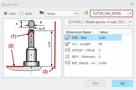
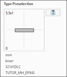
- Click OK to leave the dialog box.The preselected ejector pin information will be displayed in the dialog.
Add predefined Ejector Pin dynamically
- Click
 to start defining a new ejector pin. The view rotates to the bottom.
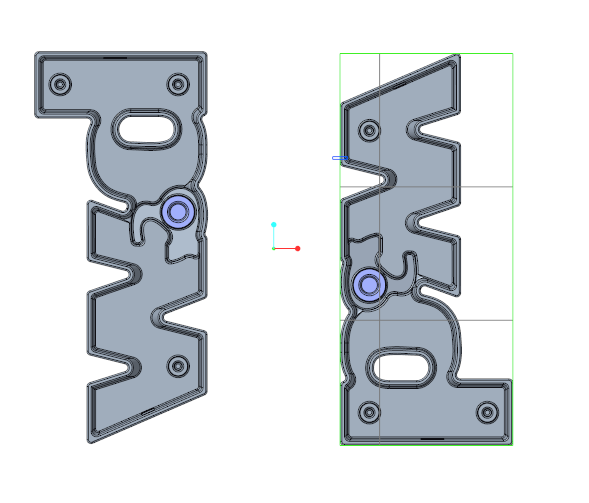
- In the graphics window, the ejector pin cross section is previewed at the pointer position.
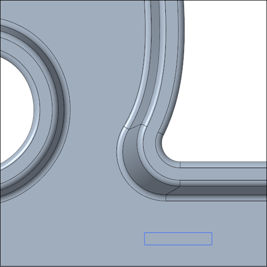
- Click anywhere within the outline boundaries of the reference to define the intersecting point of the ejector pin with the
reference model.
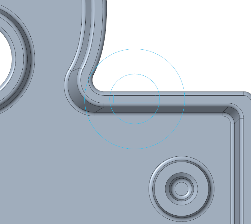 The point feature and a layout curve are assembled to the plate.The layout curve represents the dimensions of the predefined ejector pin.The Ejector Pin dialog box opens.The previously preselected type is displayed in the Ejector Pin dialog box.
 - Click OK to complete component predefinition and close the dialog box for the component. The ejector pin will be added to the list of ejector pins.
- Click middle-mouse button to leave the interactive predefinition.
Working with list of Ejector Pins
As ejector pins are created, they appear in the bottom of the Ejector Pin Designer dialog box.
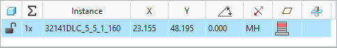
- Double-click on X value and set it to 23.100
- Double-click one Y value and set it to 48.000. The curve will be moved top the new position. In case the position is invalid the old value remains.
Assemble the predefined Ejector Pins
- Click
 Update Ejector Pins in 3DThe ejector pins will be assembled and create the cut-outs in all interfering plates and components.
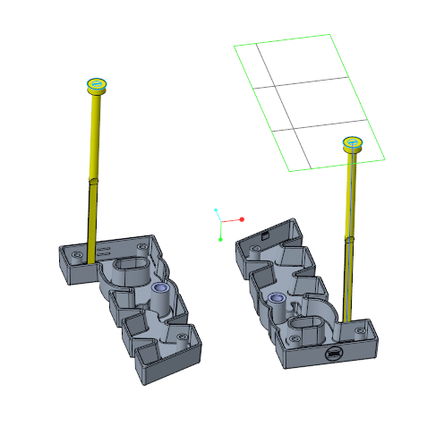
Delete Ejector Pins
- Click with right-mouse button on the recently created ejector pin in the table and click
 Delete Ejector PinThe ejector pin, the component, and the ejector pin cut out are deleted from the mold base.
Add predefined Flat Ejector Pins with 0° Rotation on existing points
- Make sure all points in the reference model are visible.
- Click
 to predefine a new ejector pin on existing points. the view is rotated to the bottom view.The Selection Window opens.
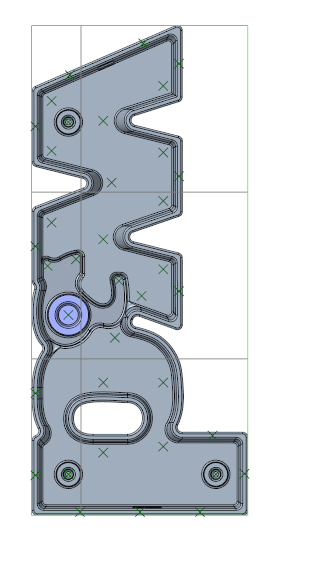
- In the graphics widow select a point from the multiple point feature PNTS_FLAT_EPIN_5-5X1MM_0-DEG.The point feature and a layout curve are assembled to the plate.
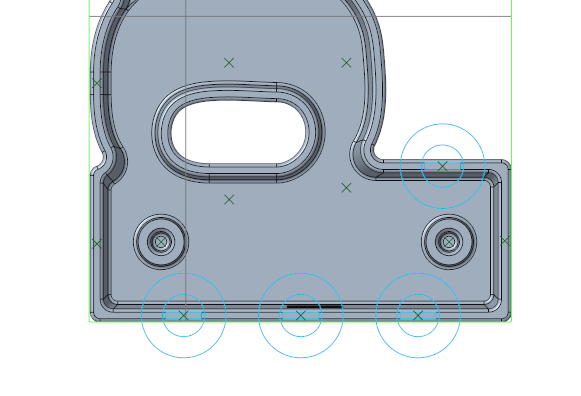
- Make sure Trim to quilt/refmodel is activated.
- Click OK to finish the predefinition.The ejector pins are added to list.
Add predefined Flat Ejector Pins with 90° Rotation on existing points
- Click to predefine a new ejector pin on existing points. The Selection Window opens.
- In the graphics widow select a point from the multiple point featurePNTS_FLAT_EPIN_5-5X1MM_90-DEG.The point feature and a layout curve are assembled to the plate.
- Enter 90 for REF_ANGLE.
- Click
 Preview to update the layout curves.
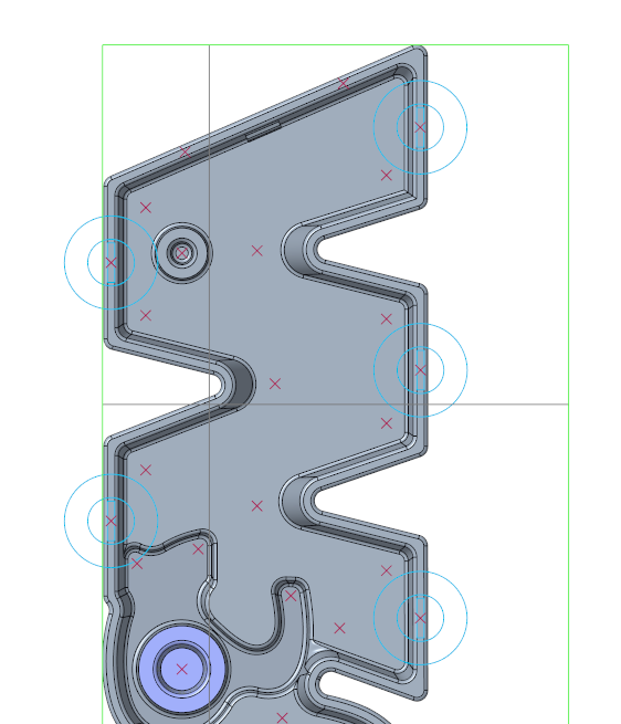
- Make sure Trim to quilt/refmodel is activated.
- Click OK to finish the predefinition.The ejector pins are added to list.
Add predefined Flat Ejector Pins with 23° Rotation on existing points
- Click to predefine a new ejector pin on existing points. The Selection Window opens.
- In the graphics widow select a point from the multiple point feature PNTS_FLAT_EPIN_5-5X1MM_113-DEG.The point feature and a layout curve are assembled to the plate.
- Enter 23 for REF_ANGLE.
- Click Preview to update the layout curves.
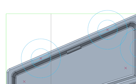
- Make sure Trim to quilt/refmodel is activated.
- Click OK to finish the predefinition.The ejector pins are added to list.
Assemble the Flat Ejector Pins on Existing Points
- Click Update Ejector Pins in 3D.The ejector pins will be assembled and create the cut-outs in all interfering plates and components.
- Leave the Ejector Pin Designer with OK.