To Assemble Support Pillars on Mouse Pick Points
Download 45 To Assemble Support Pillars on Mouse Pick Points to start from with this chapter.
Assemble the Support Pillars
- Open the TUTOR_MH.ASM assembly.
- Click EMX Components Components
 Support Pillar.
 - Select E1510 from the Type pull-down menu.
- Select 40 mm for DM1.
- Define the references.
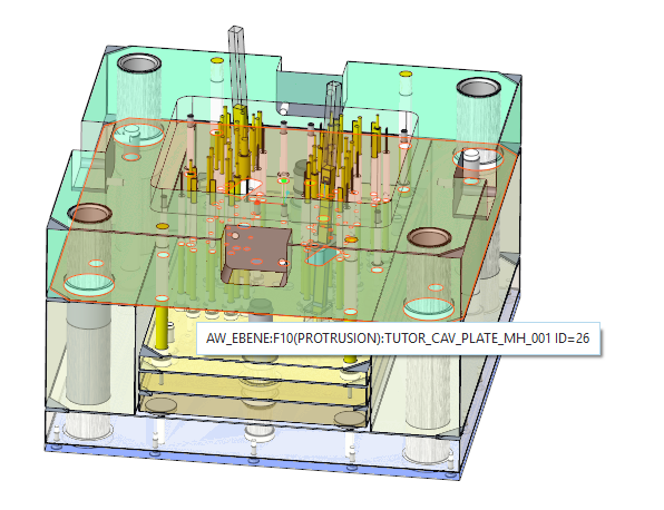
- As (2) Surface select the bottom side of the cavity plate TUTOR_CAV_PLATE_MH_001.PRT.
- As(3) Second Surface select the top side of the clamping plate .
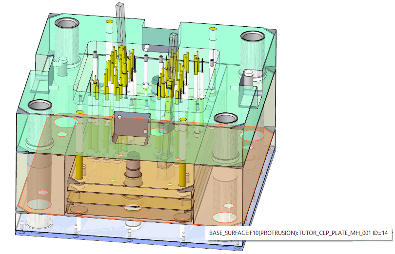 The REF1 Reference Distance displays the offset between the plates.
- As (2) Surface select the bottom side of the cavity plate TUTOR_CAV_PLATE_MH_001.PRT.
- Click the
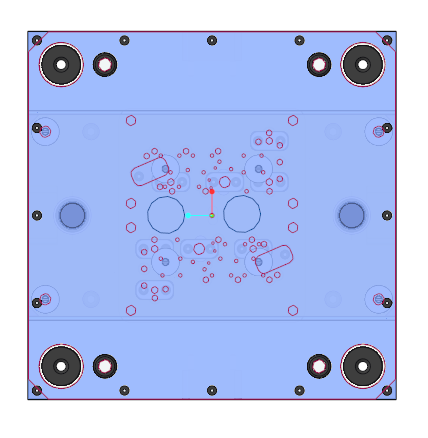
 Mouse Pick Placement. The graphics window is reorientated to top view.The Support Pillar dialog box is disabled now unless you have finished the placement operation.A Circle with the Diameter value 40 mm is drawn at the mouse position in the 3D graphics window.
 - Add 2 points with the left mouse button.
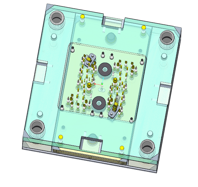
- Stop the placement loop by pressing middle-mouse button.New Points are created using the (2) Surface as placement plane.The MOLDBASE_X_Z and MOLDBASE_Y_Z datum planes of the skeleton are used as placement reference.
- Make sure the option Toggle Direction is activated.
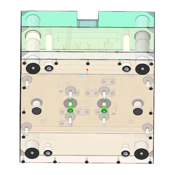
- Close the Support Pillar dialog box with OK.Two new support pillars are created.
- Modify the previously created Datum Point feature.
- Set the Offset References values to (50;0) and (-50;0)mm.
Assemble the Screws for the Support Pillars
- Assemble screws E1200/10x40 by using the previously create datums as point reference.As surface references select:
- the bottom surface of the moving half clamping plate.
- the bottom surface of the support pillars.
- Close TUTOR_MH.ASM to return to the main assembly.