To Assemble Side Interlocks
Download 23_To Assemble Side Interlocks to start from with this chapter.
Modify the Side Interlock Pattern
- Open Mold Base Definition dialog
 .
. - Click
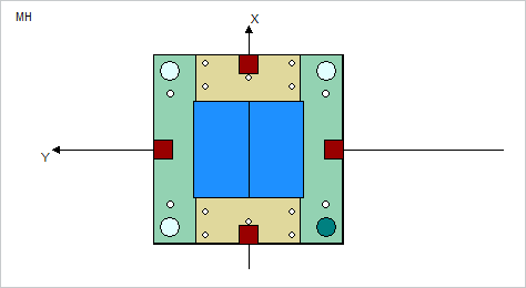
 Top to switch to the top view.
 - Double-click on Side Interlock in the summary tree.The Side Interlock pattern dialog box opens.The Pattern size values in the Side interlock dialog box are set to the current mold base size by default.
- Enter Quantity to 2 in both X- and Y-direction.
- Select
 to update the number of instances.
 - Check the placement of the Side Interlocks in the Top View of the Mold Base Definition dialog box.
- Click OK to close the dialog and regenerate the pattern in the skeleton model.
Define the Side Interlock Properties
- Select Side Interlock from the Equipment pull-down.
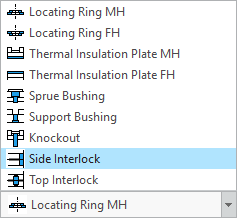 The Side Interlock dialog box opens.
 - Select the main assembly TUTOR_SHARED as target subassembly.
- Select hasco from the supplier pull down list.
- Select Z07_17 from the types pull down list.
- Select a value of 46 mm for B_.
- Do not change any other default settings in the Side Interlock dialog box.
- Click OK to close the Side Interlock dialog box.
- Close the Mold Base Definition with Close.
Assemble Predefined Screws in Side Interlock Assembly
For the Hasco Z07/17 side interlock assembly screws are already predefined.
- Click EMX Components Component Handling
 Assemble predefined components.The Selection dialog appears.
 - Select the subassembly TUTOR_SHARED.ASM.All predefined components within this assembly are assembled.
- Leave the selection dialog with middle-mouse button.