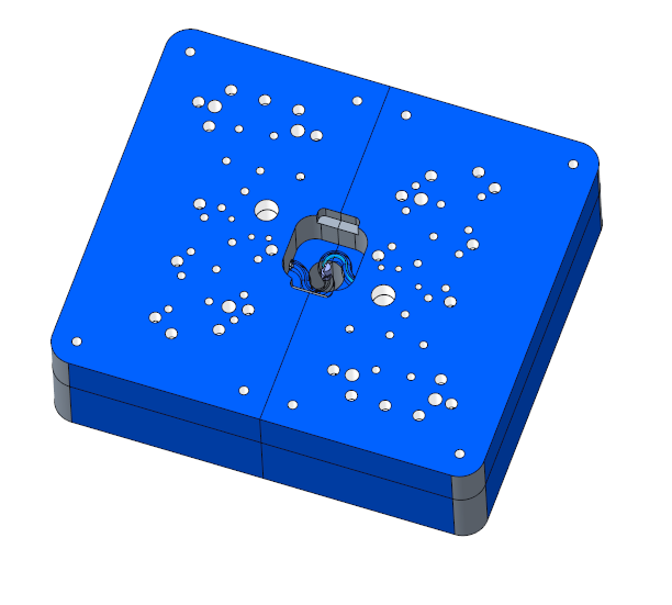
To Design the Runner
Download 42 To Design the Runner to start from with this chapter.
Create a Runner Assembly
- Click EMX Assembly Structure
 Add Subassemblies.The Subassembly dialog box opens.
 - Select TUTOR_SHARED from the Subassembly pull-down list.
- Enter TUTOR_RUNNER into the Name input panel.
- Click OK to leave the Subassembly dialog box.A new EMX Subassembly will be added to the mold base assembly.
- Open the TUTOR_SHARED.ASM assembly.
Create the Runner Quilt Surface
- Activate the TUTOR_RUNNER.ASM assembly.
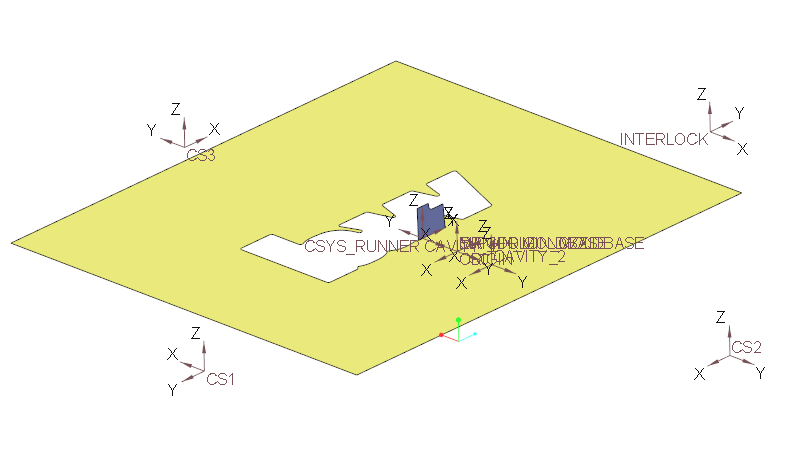
- Create a assembly dependent Copy Geometry feature which contains:
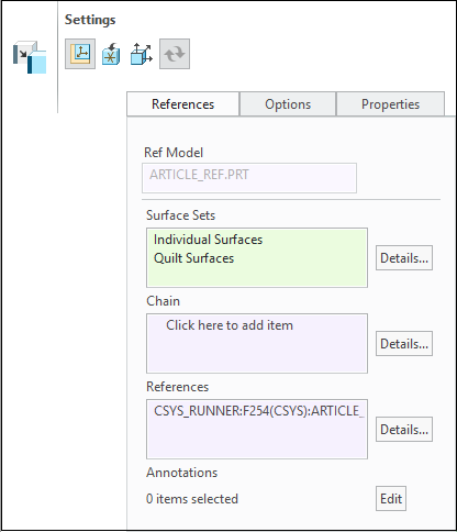
- The coordinate system CSYS_RUNNER from the ARTICLE_REF.PRT
- The relevant quilt surfaces from the article reference part. (You must be Show the Layer 00_BUW_DATUM for catch it)
- Open the TUTOR_RUNNER.ASM assembly.
- Make quilt surfaces are not hidden by layers.
Assemble the Conic Gate
- Activate the TUTOR_RUNNER.ASM assembly.
- Click EMX Components Library
 Assemble.The Library Component dialog box opens.
 - Select runner folder from the library tree.
- Double-click on gate_cone.The Component tab is activated.
- As first placement reference (1) CSYS select the CSYS_RUNNER.
- Set gate diameter DM to 1.8 mm.
- Set H height value to 4 mm.
- Click on
 Preview to display the gate in the graphics window.
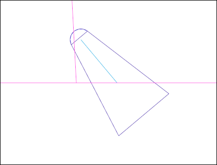
- Click OK to assembled the gate cone part. Make sure all quilt surfaces are visible.
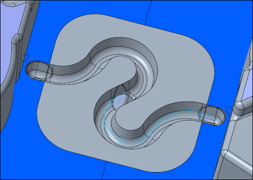
Create the Sprue Sketch
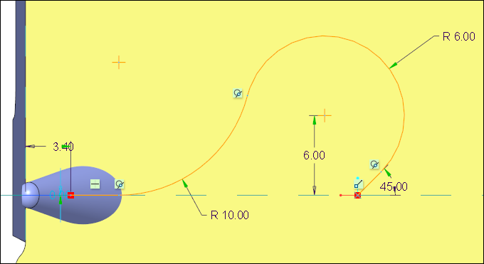
- Create a Sketch on MOLDBASE_X_Y in the skeleton plane.
- Create the sketch as seen below.
Create the Sprue Channels
- Click EMX Components Library Assemble.The Library Component dialog box opens.
- Select runner folder from the library tree.
- Double-click on trapezoid_es.The Component tab is activated.
- For W select a value 5 mm.
- As first placement reference (1) Curve select a segment of the previously created sketch.
- Click OK to assemble the sprue channel.
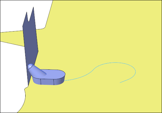
- Repeat the assembly of the trapezoid UDF for all segments of the sketched sprue curve.
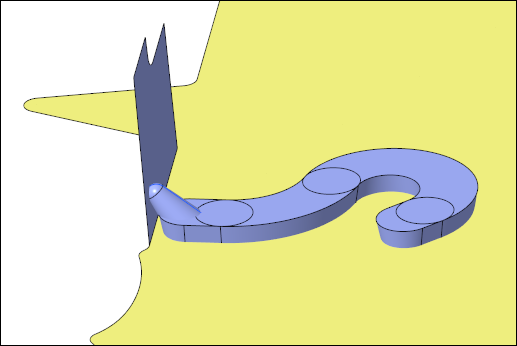
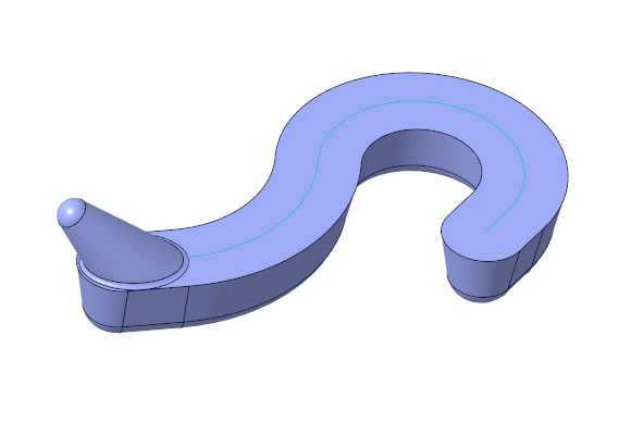
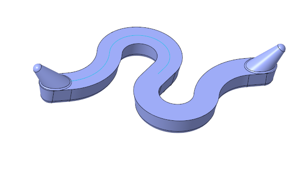
- Trim and merge the created quilt to finally retrieve the sprue.
- Create round to avoid sharp corners.
Mirror the Quilt
- Select the quilt and use Copy and Paste Special.
- Select Rotate for Settings.
- Select the AXIS_LOCATING from the TUTOR_SKELETON.PRT.
- Set a value of 180 degrees.
- Select the Options tab and disable Hide original geometry.
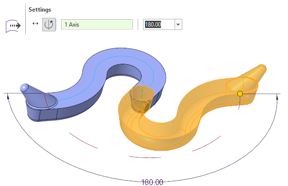
- Click OK to finish the special copy operation.
- Merge both quilt surfaces.
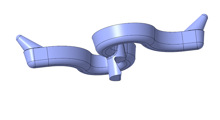
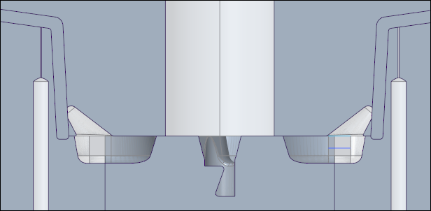
Create the Sprue Puller Pin Channel
- Click EMX Components Library Assemble.The Library Component dialog box opens.
- Select runner folder from the library tree.
- Double-click on sprue_puller_channel.The Component tab is activated.
- As first placement reference (1) CSYS select the ORIGIN_MOLDBASE from the TUTOR_SKELETON.PRT model.
- Click OK to assemble the sprue puller pin channel.
- Merge the quilts.
- Create rounds to avoid sharp corners.
- Close TUTOR_RUNNER.ASM to return to the TUTOR_SHARED.ASM.
Design the Sprue Retainer Bush
- Create a new part TUTOR_RETAIN_BUSH.PRT and assemble it to the ORIGIN_MOLDBASE.
- Design the part using default functionality.
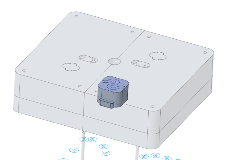 The major outline in this example is 38x38 mm.
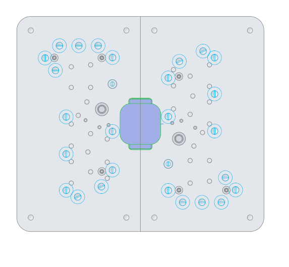
- Create to quilt surface which can be used for Solidify operation.
- Create Soldify features in:
- MOLD_VOL_ES_1.PRT
- MOLD_VOL_ES_2.PRT
Create the Solidify Cuts for the Runner in Insert Parts
- Create the Solidify cuts in using the runner quilt surface in:
- TUTOR_RETAIN_BUSH.PRT
- MOLD_VOL_ES_1.PRT
- MOLD_VOL_ES_2.PRT
- MOLD_VOL_IS_1.PRT
- MOLD_VOL_IS_2.PRT
Assemble the Sprue Puller Pin
- Click EMX Components
 Ejector Pin.The Ejector Pin dialog box opens.
 - Select knarr from the Supplier pull-down list.
- Select 37111 from the Types pull-down list.
- Set the DM1 value to 5 mm.
- Define the references.
- For (1) Point select the point PULLER_PIN from the TUTOR_SKELETON.PRT model.The LG1 value is automatically set to 160 mm.
- For (1) Point select the point PULLER_PIN from the TUTOR_SKELETON.PRT model.
- Activate Trim to quilt/refmodel option.
- Select
 Rotfix1 from the Fix Rotation pull-down list.
 - Make sure to set the D1 value in the UDF Dimensions to 5.000 mm m the Fix Rotation pull-down list, otherwise the UDF can not be assembled.
- Close the Ejector Pin dialog box with OK.The pin is assembled and trimmed.Cut outs are added to the TUTOR_RETAIN_BUSH.PRT.
- Close the TUTOR_SHARED.ASM to return to the main assembly.
- Click from the overflow menu.The missing bores for the puller pin are added to the mold base assembly.