To Understand whether Cutouts in Plates are driven by Component or Plate
Download 00_to_cut_or_not_to_cut to start from with this chapter.
Hide Clamping Screws Plate Feature in Plate
- Load the assembly to_cut_or_not_to_cut.asm.
- Enter the Mold Base Definition dialog box with
 .
.
- RMB on the F10 plate in the side view.
- Select the CLP_BORE_CB feature in the Plate dialog box to toggle its visibility from
 to
to  .
.
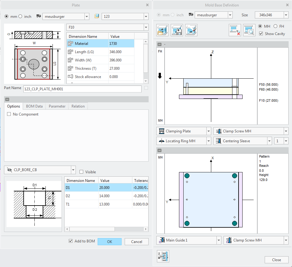
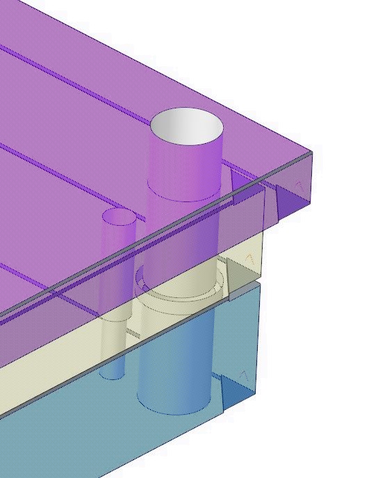
- Close the Plate dialog box with OK.Now the default cutout for the clamping screw is gone from the clamping plate.
Add Clamping Screws
- Select Clamp Screw MH from the screw list.The Diameter and Length in the Screw dialog box are set by the mold base data from the size_346x346 plate file.
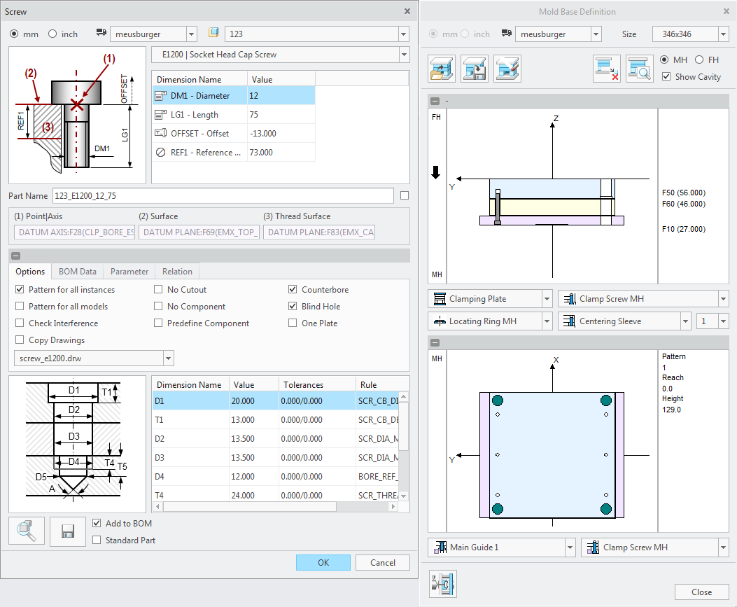
- Leave the Screw dialog box with OKAs NO counter bore in the F10 plate exist, an additional bore is added to the clamping plate CUT_CLP_PLATE_MH000.PRT. This
bore is now driven by the screw cut out UDF, NOT by the plate size file.On the other side the counter bores in the plate F50 and F60 already existed. This features are driven by the plate size file.Therefore NO additional cut outs are added to the F50 and F60 plates.
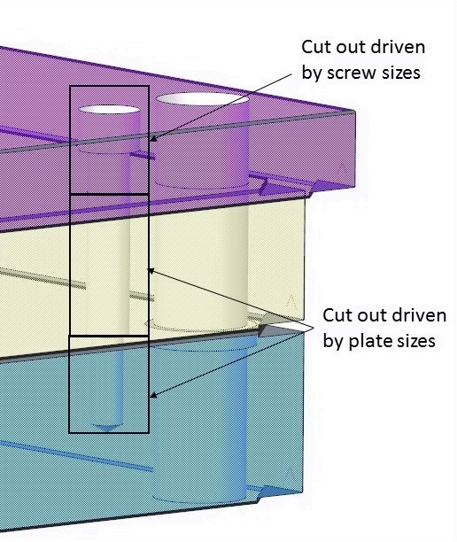
The additional UDFs counter bore in the F10 plate is driven by the UDF’s dimensions from the Screw dialog box.
The bores in F50 and F60 are driven by the feature dimensions in the Plate dialog box.
If you use P-Plates without any predefined cutouts and bores you can realized this by setting the EMX Option USE_P_PLATE_STACK to YES. Then all cutouts are generated by screws, leader pins individually.
Reset the Normal State
- RMB on the F10 plate in the side view.
- Select the CLP_BORE feature in the Plate dialog box to toggle its visibility from to .
- Close the Plate dialog box with OK.
- RMB on the clamping screw MH in the Side View.
- Assemble the screw again WITHOUT ...Counter Bore.
- ... and the assemble the screw again WITH Counter Bore.Now all cutouts in all plates are driven by the Plate size data only.