To Assemble the Stop System
Download 25 To Assemble the Stop System to start from with this chapter.
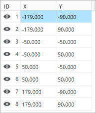
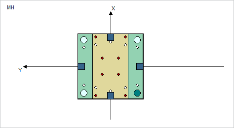
Define the Stop System Pattern
- Open Mold Base Definition dialog box.
- Click
 Top to switch to the top view.
 - Double-click on Stop System MH in the summary tree.The Stop System MH pattern dialog box opens.For supplier meusburger no default pattern information is defined in the catalog.
- Set X Quantity to 4.
- Set Y Quantity to 2.
- Enter Pattern Size 358 and 180.
- Click
 to update the number of instances.
 - Change instance 3 to 6 as seen in the image below.
- In the Mold Base Definition dialog box deselect the option Show Cavity to display the full stop system pattern in the top view.
- Click OK to close the pattern dialog.
- Leave the Mold Base Definition dialog box with Close.
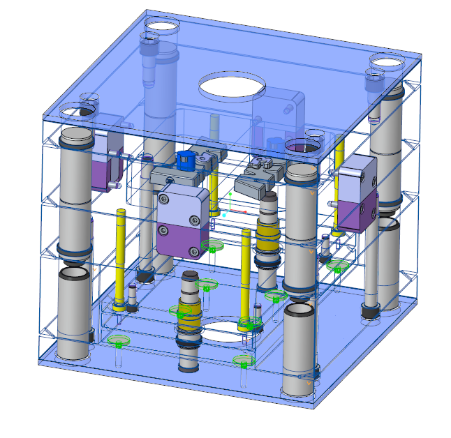
To Assemble the Stop Pins
- Open the moving half assembly TUTOR_MH.ASM.
- Click EMX Components Components
 Stop pin.The Stop pin dialog box opens.
 - Set the DM3 value to 30 mm.
- As the first assembly reference (1) Point|Axis select the first axis instance STOP_BORE from the stop system pattern in the TUTOR_SKELETON model.
- As the second assembly reference (2) Surface select the top surface of the clamping plate.
- Switch to the Options tab and enable the option Pattern for all instances.
- Click
 to preview the stop pins.
 - Click OK to leave the Stop Disc dialog box.The Stop System will be added to the mold base.
- Close the TUTOR_MH.ASM to return to the main assembly.
Remove Additional Stop Pin Bores from Ejector Base Plate
The new stop bore instance should not be added to the ejector base plate. They need to be removed from the model
- Open the ejector base plate TUTOR_EJBASE_MH_001.PRT.
- Modify the pattern STOP_DISC_BORE.
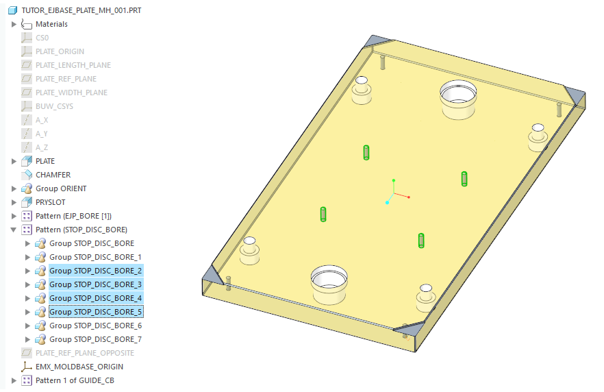
- Suppress the instances 3 to 6.
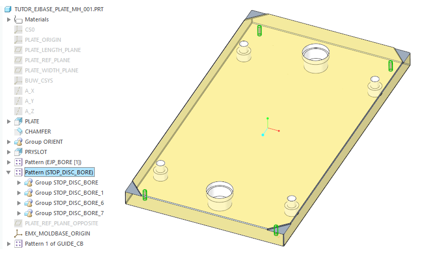
- Close TUTOR_EJBASE_MH_001.PRT to return to the main assembly.