To Assemble the Sprue Bushings
Download 27 To Assemble the Sprue Bushings to start from with this chapter.
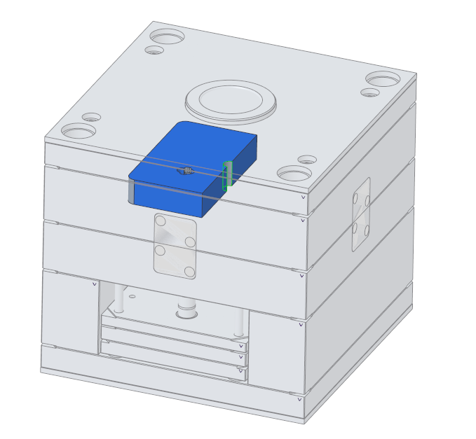
Assemble the Sprue Bushing
- Open the fixed half assembly TUTOR_FH.ASM.
- Click EMX Components Components
 Sprue BushingThe Sprue Bushing dialog box appears.
 - Select E1605 from the Types pull down list.
- Set the D_2 value to 18.
- Set the OFFSET value to 4.The sprue bush will interfere with the clamping plate.
- Set LG1 to 76. The length needs to set to a value that the sprue bush reaches the splitting plane of the mold.
- As the first assembly reference (1) Axis|Point select the AXIS_LOCATING from the TUTOR_SKELETON.PRT model.
- As the second reference (2) Surface select the top surface of the cavity plate.
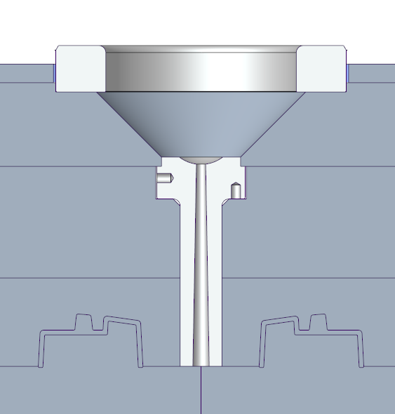
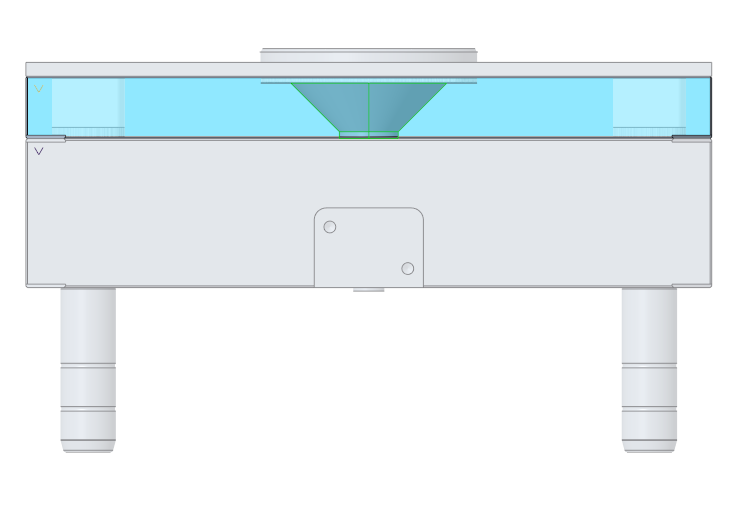
- Close the Sprue Bushing dialog with OK.The sprue bush is assembled to the fixed half and cut-outs are added to the cavity plate.However, additional cutouts are required in the clamping plate and the cavity insert parts, which will be designed in the following steps.
Shorten the Sprue Bush
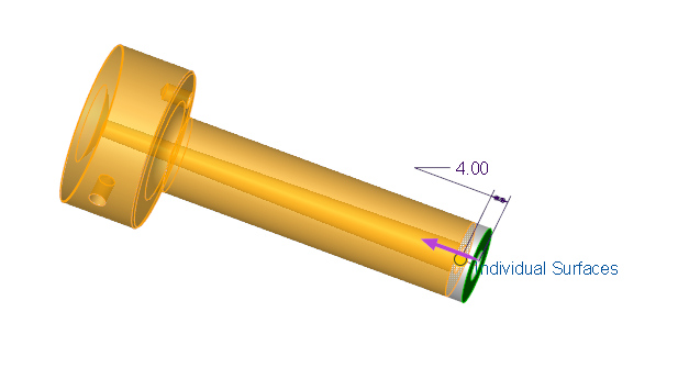
- Open the TUTOR_E1605_18_76_4.PRT.
- Create an Offset feature to shorten the sprue bushing about 4 mm.
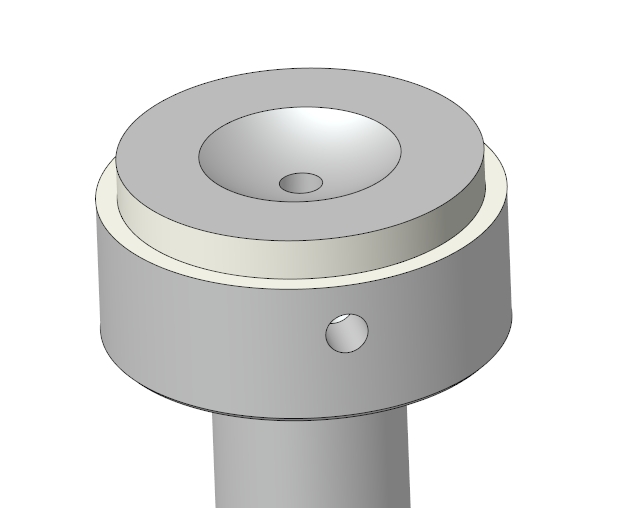
Create a Groove for fixing the Sprue Bush in Clamping Plate
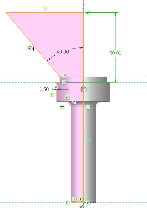
- Create a groove of 2x4 mm by using a Revolve feature.
Create a Quilt Surface Additional Cut-Outs
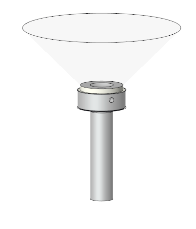
- Create a quilt surface with a Revolve feature.
- Set the quilt surface color to transparent.
- Close the sprue bushing TUTOR_E1605_18_76.PRT model.
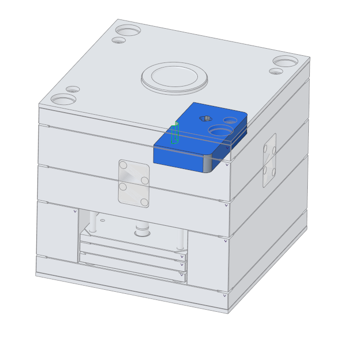
Create Cut-Out in Clamping Plate
- Activate the clamping plate TUTOR_CLP_FH_001.PRT
- Select the previously create quilt surface and create a
 Solidify feature with Remove material option enable
- Activate TUTOR_FH.ASM
- Close TUTOR_FH.ASM and return to the main assembly.
Create Cut-Outs in Cavity Insert Partse
- Within the main assembly activate the insert parts MOLD_VOL_IS_1.PRT within the first cavity insert assembly MFG_1.ASM.
- Select the previously create quilt surface in the sprue bushing model and create a Solidify feature with Remove material option enable
- Repeat the steps for MOLD_VOL_IS_2.PRT.
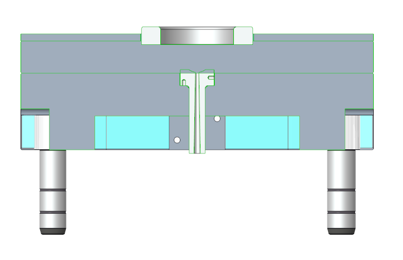
- Activate TUTORORIAL.ASM. The Sprue bushing is now full placed.