Interlude: Update Existing Ejector Pins
Download 41 Interlude Update Existing Ejector Pins to start from with this chapter.
Modify the Cavity Plate Thickness on the Moving Half
- Click EMX Assembly Mold Base
 Assembly Definition. The Mold Base Definition dialog box opens.
 - Double-click on the moving half cavity plate in the side view of Mold Base Definition.The Plate dialog box opens.
- Change the Thickness to 86 .
- Apply the modifications to the plate with OK.
- Close the Assembly Definition with Close.
- Click EMX Assembly View Show
 Moving Half.
 - Hide of the reference models.
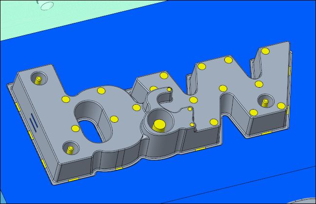
 The following problems can be discovered:
- Ejector pins with the option Auto Length are too short.The length value in the ejector pin model is not regenerating automatically.
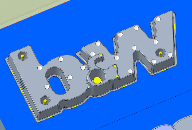
- Ejector pin models with the option Trim to quilt/refmodel have a correct length. The
 Solidify and
  Trim to geometry feature regenerating,
- In both case the order number can be incorrect if the new required length exceeds the nominal length of the selected instance.
- Ejector pins with the option Auto Length are too short.
Update the Ejector Pins
- Click EMX Components Ejector Pin
 Update existing ejector pins. The Update Existing Ejector Pins dialog box opens.
 - Click Update.The update procedure is started and all ejector pins are regenerated.
- Click OK to leave the dialog box.