To Edit the Bill of Materials
The General Bill of Material Structure
The bill of material (BOM) generally displays information about parts and assemblies of the mold base as parameter values.
- Select
 to open the BOM.
While most of the parameters can be customized, the first 3 columns of the BOM table are not changeable.
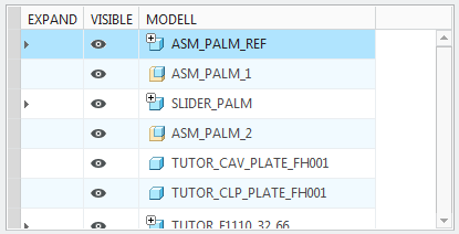
- The EXPAND column can be used to expand summarized components.
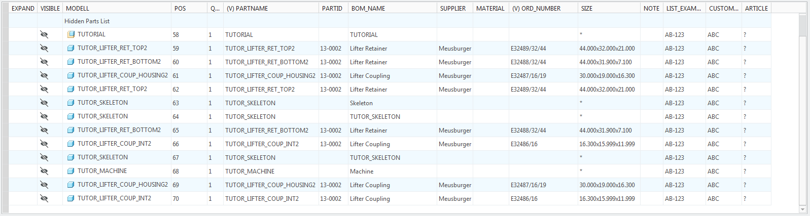
- By switching the VISIBLE entry from
 to
to  the component will be added to the Hidden Area at the bottom of the BOM. This can be useful to exclude parts like workpieces or subassemblies.
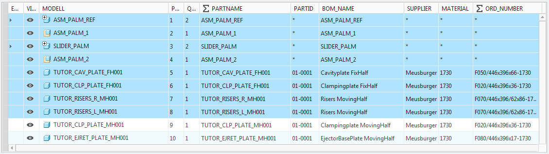
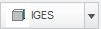
- In the MODEL column the component type and the component name are displayed.Parts and assemblies are displayed with different icons
 and
and  .
In case a component occurs multiple times in the mold base the parent is highlighted with a tiny
.
In case a component occurs multiple times in the mold base the parent is highlighted with a tiny .
.
Customize the Parameters for the BOM
The Bill of Material can be modified to the customers needs. Different parameters can be displayed and handled depending on
the configuration.
- Open the EMX Options
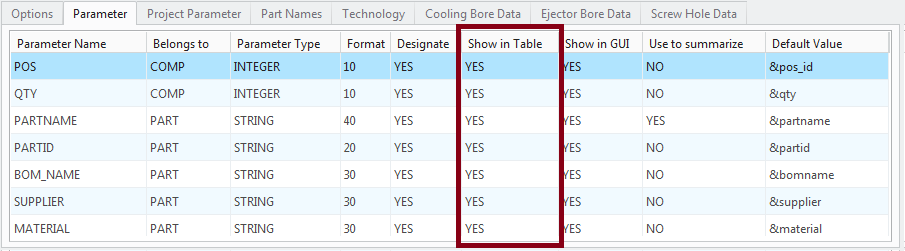
 and switch to the tab Parameter.By default EMX offers a list of parameters as seen in the picture below.
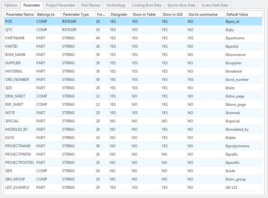
All parameters which are defined in the Parameters tab will be shown in the BOM if their entry Show In GUI is set to YES.
There are some important parameters and their Default Values that are explained here.
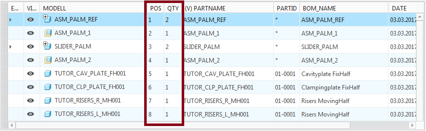
- POS: To this parameter the default value &pos_id is assigned. This default value describes the position of the component in the BOM list. If this parameter does not exist
in the BOM it is not possible to display all components in the right order.Do not change this parameter entry manually!
- QTY: This parameter represents the quantity of the components and describes how often they are assembled to the mold base. It
is important that the Default Value &qty is assigned. If this parameter does not exist the summarizing of components which occur multiple times in the mold base does
not work.Do not change this parameter entry manually!
- MATERIAL: EMX does not only provide the material as a STRING-Parameter, it will also set a Creo Material to every model that is assembled
by EMX. It is important that the Default Value &material is assigned.
For any other parameter customization take the default parameter settings as a reference. There are several other default
values that can be assigned to parameters.
Following default values for EMX Parameters are available.
- &partname: Use this parameter default value to assign the name of the Creo part or assembly to the parameter.
- &partid: This default value assigns an unique ID string to the parameter. This ID string can be customized individually. For each
component template a rule for the part id is defined in the Part Names tab of the EMX Options .
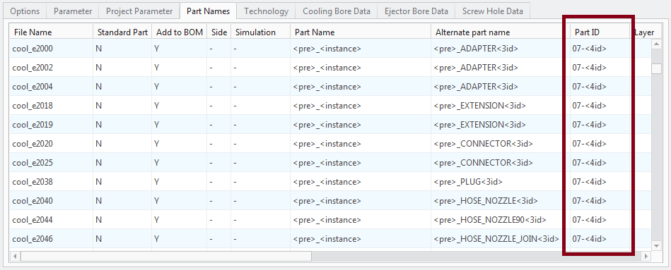 In the default configuration the part name ID has 7 digits. Beginning with a 2 digits number that represents the EMX component type (e.g. 07 stands for cooling components). The last 4 digits are a simple integer variable which increments with any newly assembled component of this type.If the EMX Option SORT_BOM_WITH_PARTID is set to YES. EMX will use this part ID string to sort the BOM. This can be very handy because all components are then listed by type. Plates with 01, Screws with 02, Guides with 03, Ejector Pins with 04, Equipment with 05, Support Pillars with 06, Cooling Components with 07, Slider with 11 etc.
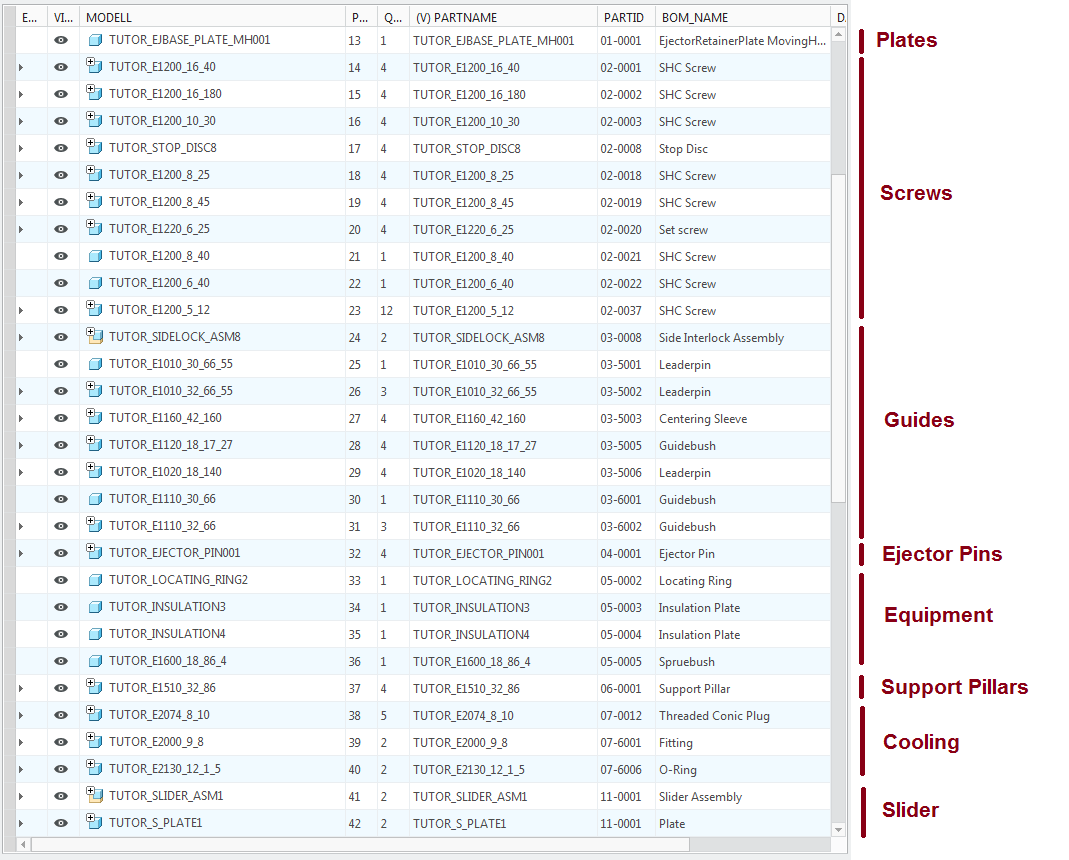
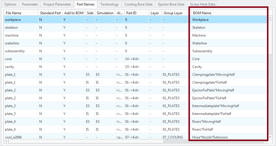
- &bomname: This default value assigns a descriptions which can also be customized in the Part Names tab of the EMX Options to the parameter.
- &supplier: Important default value, which assigns the supplier of a component to the parameter.
- &ord_number: Important default value, which assigns the order number of a component to the parameter.
- &size: EMX comes with an algorithm to calculate the outline of each part in the mold base. Click
 to start this calculation. EMX writes all outline values to the size parameter.
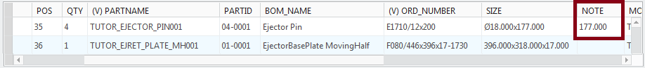
- &remark: EMX uses this default value to write notes into the BOM. For ejector pins and baffle cooling components the trimmed length
is written to this parameter. In this example the ordered length of the ejector pin is 200 mm. The trimmed length is 177 mm.
- &modeled_by: The designer defined in the Project dialog box is written to this parameter.
- &date: The date defined in the Project dialog box is written to this parameter.
- &projectname: The project name defined in the Project dialog box is written to this parameter.
- &prefix:The project prefix defined in the Project dialog box is written to this parameter.
- &postfix: The project post fix defined in the Project dialog box is written to this parameter.
- &side: The side fixed or moving half which the component is assigned to is written to this parameter.
- &sim_group: the simulation group for the opening simulation is assigned to this parameter.
- &ptc_common_name: The PTC_COMMON_NAME value is assigned to this parameter.
Summarize Equal Components in BOM
Define the criteria to sum up the components in the BOM.
- Open the EMX Options and switch to the tab Parameter.In the Parameter tab the row Use to summarize can be found.
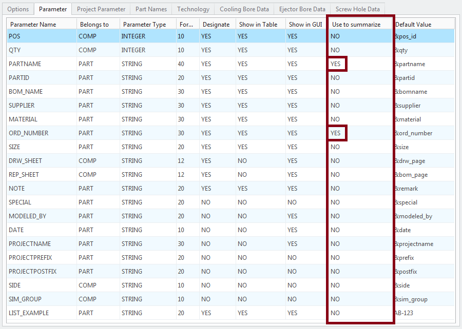 By default EMX uses the parameters PARTNAME with a default value of &partname and the parameter ORD_NUMBER with an assigned default value &ord_number to summarize the components.This means: If a component has the same value in PARTNAME and in ORD_NUMBER EMX will summarize them in just one line of the BOM.
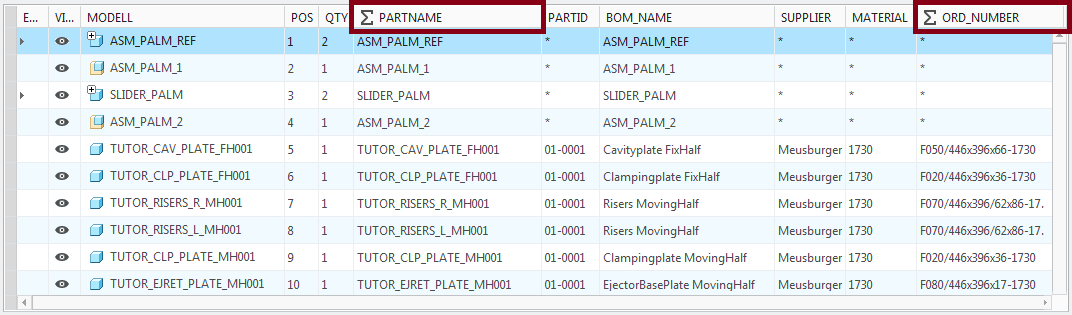

Edit Parameters individually
- Double-Click
 in the row of a summarized component. This will expand all single entries.
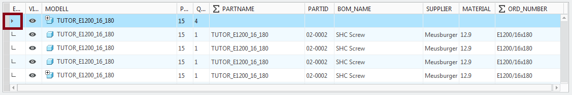 Parameters can be edited manually by Double-Click the certain entry in the BOM.
 - Edit the Parameter ORD_NUMBER of one of the components manually.
- Click Refresh
 .Remember that the parameter ORD_NUMBER was used to summarize the components.Even if the PARTNAME parameter has still the same value, the ORD_NUMBER value is now different. As a result EMX will not summarize the component any more in the BOM.
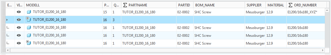 It is possible to edit all entries of the summarized components at once. Simply Double-Click the desired entry of the component row while it is collapsed.
Do not Show Parameters in BOM
- Open the EMX Options and switch to the tab Parameter.The flag Show in table can be set for each parameter individually. If the flag is set to NO the parameter will not be displayed in the BOM.
Working with the BOM
After finishing the mold base the BOM can be edited by the designer via a variety of tools.
It is possible to select multiple components with Ctrl or Shift
- Select a couple of rows using the Shift key.
- Use the RMB menu and Copy-And-Paste functionality to move them to another position in the BOM.
- You can also move the selected components up or down step-by-step with
 and
and  .
. - Toggle the VISIBLE flag for multiple components at the same time by using the RMB menu and the Show/Hide items feature.
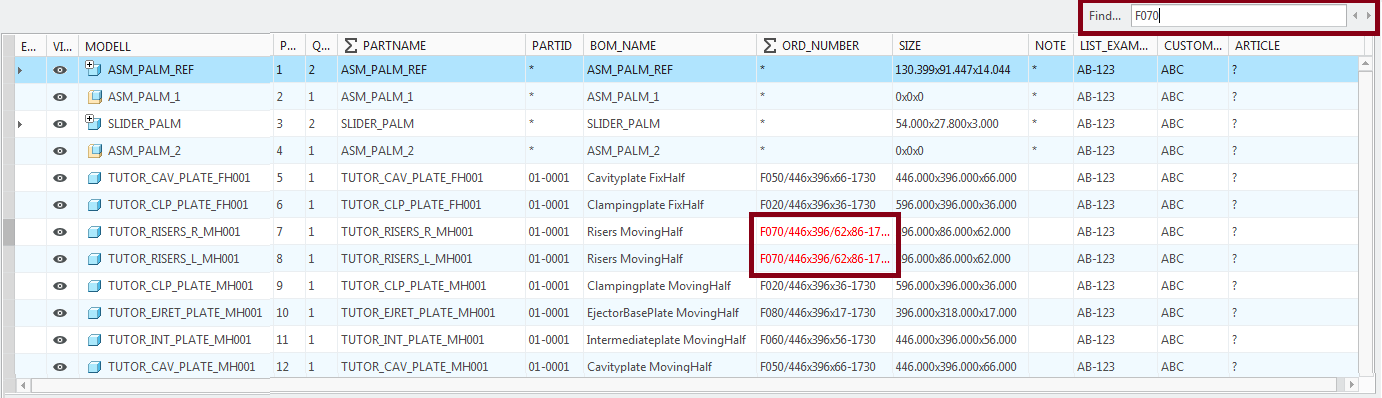
- Find the Find feature it is easy to find entries in the table.. All found entries are highlighted in red color.
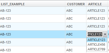
Create a Quick Selection pull down menu with sel_list.txt
- To define a list of values (like for ARTICLE or LIST_EXAMPLE), edit the file /configuration/sel_list.txt as follows:
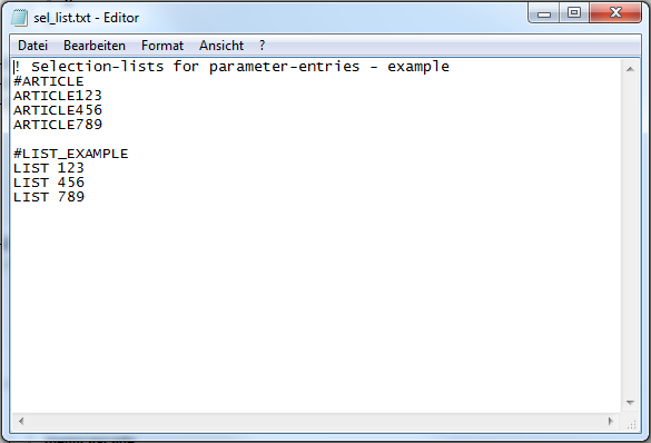
- Identify the Parameter with a "#"-symbol. All following lines are the values that will be displayed.
- Identify the Parameter with a "#"-symbol. All following lines are the values that will be displayed.
Recalculate Component Size
The Size of a component can be assigned to a parameter with the default value &size. By Default EMX adds the parameter SIZE to all components.
The size is computed by an algorithm which uses the outline of the model.
With this calculation process can be started again.
this calculation process can be started again.
Export neutral 3D model files from BOM
With EMX you can export neutral 3D file formats as STEP and IGES from the BOM dialog.
- Select a component in the list and specify the file format
 .
. - Export the file with
 .The neutral 3D file will be written to the working directory.
Export neutral 2D drawing files from BOM
Drawings can also be exported in the neutral file formats PDF and DXF.
This can only be done in case a drawing exists.
Additionally the export can only work properly if the EMX Option CHECK_DWG_WHEN_OPEN_BOM is set to YES.
By default this is set to NO as checking for drawings can take very long for large assemblies.
- Set this option to YES.
- Return to the BOM dialog. In case a drawing for the component was found in the working directory a symbol will be displayed in the MODEL column.
- Select one of these components and specify the desired file format.
- Export the file with .The PDF file will be written to the working directory.
Export BOM to a text file
The content of the BOM can be exported to a specified text file.
- Click
 to export the text file to the working directory
Export BOM to a xml file
The content of the BOM can be exported to a specified xml file.
- Click
 to export the text file to the working directory
Copy/Paste content to Excel
The BOM content can be copied and pasted to Excel.
- Click
 to export the content to the Clipboard.
- Paste the content to an Excel worksheet.
Exclude all assemblies from the BOM
Usually the assemblies of a Creo Moldbase do not appear in the BOM. They are used for structural reasons only. Right now models
like ASM_PALM_1.ASM or TUTOR_STOP_ASM2 are still visible in the BOM. Instead of changing their visibility status manually, you can set the EMX Option EMX_HIDE_ASSEMBLIES_IN_BOM to YES.
Include IDs as prefix in component names
If the EMX Option PART_RENAME_FORMAT is set to a wildcard including <pos_id> and/or <partid>, two extra functions will appear in the BOM dialog box.
With  the selected models will be renamed to the new name defined by this wildcard.
the selected models will be renamed to the new name defined by this wildcard.
With  this renaming is set back.
this renaming is set back.