To Assemble Trimmed Ejector Pins
Download 33 To Assemble Trimmed Ejector Pins to start from with this chapter.
- Click EMX Assembly View
 Wireframe Style.
 - Click EMX Assembly View Show
 Moving Half.
 - Click EMX Components
 Ejector Pin.The Ejector Pin dialog box opens.The TUTOR_MH_EPINS assembly is preselected.
 - Select knarr from the Supplier pull-down list.
- Select 36111 from the Types pull-down list.
- Set the DM1 value to 2 mm.
- Define the references
- For (1) Point select a point from the multi point feature PNTS_SHOULDERED_EPINS_2MM in the ARTICLE_REF.PRT model.The LG1 value is automatically set to 200 mm.
- For (1) Point select a point from the multi point feature PNTS_SHOULDERED_EPINS_2MM in the ARTICLE_REF.PRT model.
- Activate Trim to quilt/refmodel option.
- Select
 Rotfix1 from the Fix Rotation pull-down list.The former counter bore in the ejector retainer plate is replaced by a new UDF with the rotation fix geometry. The ejector pin geometry is also modified to fit to the new cutout.
 - Switch to the Options tab and activate the Pattern for all models option.
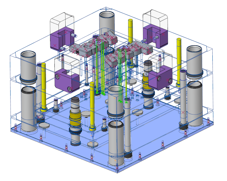
- Close the Ejector Pin dialog box with OK.The cut-outs are generated and the ejector pin is assembled.
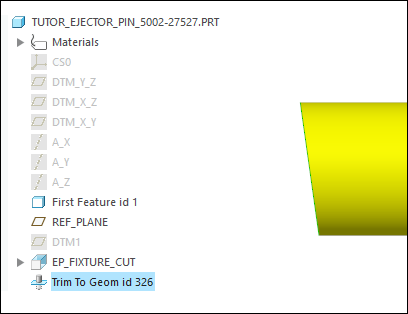
 A
A Trim To Geom feature is added to each ejector pin to trim it against the reference model.
 The rotation fixture UDF is added to the ejector retainer plate and the ejector models a modified.